It would be interesting to hear what the grandees think of the original design, from the magazine article.
To my marginally trained eye, it looks to be elegant in its simplicity, with an echo of the biasing arrangement of an Dynaco ST-35, and that is justified by being a source of dynamic balance between the channels to balance load on the single power supply.
Is there any reason not to build it exactly as designed?
OldHector: From my point of view, to see what can be done with it. Also I wanted to build all octal and use a DH Rectifier. And I have a tonne of iron to use up that I bought over the years, also a box of motor run caps etc. 🙂
When I first tested it (before the smoking power transformer) I thought it sounded as good as any of the amplifier circuits I clip leaded and wrote up in the noughties, which included 10Y/801a, 46, 47, 2a3, 6a4, 33, 843.
I never built the original Darling circuit though, so I have no point of reference.
I'm revisiting these low power tubes because with the speakers I'm working on I have no need for any more power in my environment. I'm using a pair of waxed birch ply Mesa TL806 "Thiele" cabinet clones with 12" Fane Ascension A60 Alnico instrument speakers, crossed over (single inductor) to a (-5dB padded) EV T35, vertically mounted in "free space" and aligned for phase. sort of like the Tone Tubby 12" in this application - The 12" Alnico Tone Tubby. It's sounding very nice in my room and very loud with 1 watt 🙂 about 100dB efficient and no peaks because I damped the 12" 's basket and magnet cover all over and wool felt damping on the cab walls. I went to town on the crossovers and used Miflex aluminium and copper foil caps and Pathaudio resistors.
Hi mikw st, thanks for the reply.
Your discussion has been very interesting, but it was also interesting to see the basis of your work.
The more I read about these minimalist low power SE amps, the more I realise I will have to start to look at speakers. I don't have so much space at the moment, so I'll have to read up on bookshelf solutions.
It feels a bit like loving good food and good wine, but then there is also wine that complements the food, and vice versa.
Cheers, Richard
Very true. Not sure what you could use for bookshelf speakers that would give enough bass and be efficient too? Anything small, highly efficient and with a big magnet will probably have a high Fs
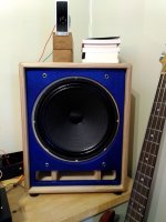
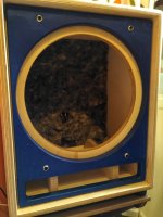
Here's a couple of pics of mine, they're not too big but probably weigh too much for a bookshelf 🙂. They are about 37 litres depending upon how the port is measured. About -6dB at 60Hz in room and they work fine against in the corners which was the main consideration in a small room.
Dimensions 47cm x 37cm x 32 cm and 15Kg each.
Attachments
Last edited:
Ok, so I did some investigation and re wired the ground connections on the PT HT secondary and 12.6v heater secondary and got the same 190v output from the filter network so I disconnected the choke's connection to the 5y3 and still got 190v HT, so I figured the only thing left was that I must have wired the secondaries out of phase. So I disconnected them and re wired again and back came the missing volts - now I have 370v at the 5y3 cathode 😱.
And lo and behold when I rewire the choke to the 5y3 tube socket, the voltage out of the choke input filter network went up to 266v, which is exactly what PSUD said it would be 🙂
So a learning experience there 🙄. Trust PSUD and check the secondary transformer winding orientation 😱.
I still have non-volume level dependent 50hz hum though, so now to work out what I did that introduced it when I replaced the original power transformer that fried. I did run another earth wire from the centre tap of the power transformer secondary directly to the chassis earth point so right now that seems the most likely culprit. I will re wire that connection to the original PSU earth point to take away the loop and see what I get 🙂
Did anyone say pull the tubes?
And let what is left run for a while. If the PT gets hot that is your problem. While unhooked check the 5V & 6.3V wdg, are they at spec while unloaded? And check the voltage of the HV wdg, one side at a time.
To isolate a problem remove as many of the other variables as possible.🙂
And let what is left run for a while. If the PT gets hot that is your problem. While unhooked check the 5V & 6.3V wdg, are they at spec while unloaded? And check the voltage of the HV wdg, one side at a time.
To isolate a problem remove as many of the other variables as possible.🙂
All windings are now at spec under load - 4.9v/12.7v and the HT both at 360. I'll run it for a bit and see how hot it gets...
Still got the mains hum though after a lot of moving ground wires and reversing the 6.3v heater wiring/reseating it etc. No ground loops I can see either 😱.
There was no hum with the original transformer that melted, could the hum be from the transformer itself?
Still got the mains hum though after a lot of moving ground wires and reversing the 6.3v heater wiring/reseating it etc. No ground loops I can see either 😱.
There was no hum with the original transformer that melted, could the hum be from the transformer itself?
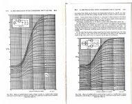
Guessing again at an outcome without thinking is a waste of your time. For a FW Rectifier under normal circumstances the relation
2*PI*f*Rl*C > 10 to 20
f is the supply frequency, Rl is the load at the first cap & C is the first cap. You can solve for a suitable cap on a 4-function calculator.
This does result in a DC output at the first cap of ~1.25X the applied AC.
This follows from the curves reproduced in RDH4. And from a lot of personal experience.🙂
Attachments
mikw st,
the choke input filter is often problematic to implement. The voltage loss is a sign that the choke input filter is working. Spare your rectifying diode and power transformer.
the choke input filter is often problematic to implement. The voltage loss is a sign that the choke input filter is working. Spare your rectifying diode and power transformer.
N101N, you're telling me not to implement it?
The only reason I did was to lose some volts in the higher secondary V PT I had in my stash while waiting for delivery of my replacement EI PT with lower secondary volts. It was quicker to desolder the input C than change the filter resistor for a higher value.
Anyway, once I corrected my wiring mistake the voltage was as required - 266v.
The problem I have now is hum. When I used the original cap input supply with the transformer that failed there was no hum. Since I installed the other transformer I got hum 1) using choke or cap input when I had the secondaries wired out of phase and 2) in choke input topology with the secondaries wired correctly.
I guess what I have to do is convert back to C input and lower the raised volts with more series resistance in the fiter stages after the choke - and see if that cures the hum. If it doesn't then its got to be the power transformer humming as I've eliminated everything else and the problem will go away with my new PT, when I receive it. I can go back to the original circuit design with cap input filter and live happily ever after. I'll have learn't a few things on the way for when I build the second monoblock.
What personal experience do you have with the choke input filter?
Well, lets have a look. I've designed & built PS from 1.5V, 0.25A to 4.5KV, One Amp regulated. Some of those were with choke input filters. Some were in audio amplifiers but others were in utility supplies for research projects. I've designed & built with toobs, Germanium & Silicon & Hybrids of those. And much experience with LEDS, PIN Diodes & Schottkys at RF. And worked for sometime in the test department where the transformers left on a railway flatcar on their way to a power station. Single & 3-phase. And certainly know how to treat the design of a 3-phase AC to DC conversion. With or without rotating machinery.
What is your experience with choke input filters & what do you want to design?🙂
My power supply for 300b mono-block se is 2uf (filmcap) 10h choke 100uf 220R 100uf @50ma current for 300b then rcrc filter @9ma for wonderful trioded ef184. The 10 henry@ 120ma choke I sourced out of china and in this configuration it works like a charm.
''I guess what I have to do is convert back to C input and lower the raised volts with more series resistance in the fiter stages after the choke - and see if that cures the hum.''-----this will be logical move pls do it and tell us the outcome.
Regards
''I guess what I have to do is convert back to C input and lower the raised volts with more series resistance in the fiter stages after the choke - and see if that cures the hum.''-----this will be logical move pls do it and tell us the outcome.
Regards
N101N, you're telling me not to implement it?
The only reason I did was to lose some volts in the higher secondary V PT I had in my stash while waiting for delivery of my replacement EI PT with lower secondary volts. It was quicker to desolder the input C than change the filter resistor for a higher value.
Anyway, once I corrected my wiring mistake the voltage was as required - 266v.
The problem I have now is hum. When I used the original cap input supply with the transformer that failed there was no hum. Since I installed the other transformer I got hum 1) using choke or cap input when I had the secondaries wired out of phase and 2) in choke input topology with the secondaries wired correctly.
I guess what I have to do is convert back to C input and lower the raised volts with more series resistance in the fiter stages after the choke - and see if that cures the hum. If it doesn't then its got to be the power transformer humming as I've eliminated everything else and the problem will go away with my new PT, when I receive it. I can go back to the original circuit design with cap input filter and live happily ever after. I'll have learn't a few things on the way for when I build the second monoblock.
You have low value caps ... have you tried using more in parallel ?
Maybe the first choke is at the point of saturation and the inductance under load is ( much ) lower ... Without measurements you don't know . This is not that simple in real life like a program simulation would tell you .
Last edited:
Hum can be from -
1 - mechanical noise - is the transformer itself actually humming? Does isolating the bolts from the chassis make a difference? Is the hum from the unit or the speakers?
2 - radiated, does moving the transformer away, rotating it or shielding it make a difference?
3 - insufficient filtering.
4 - ground loops.
You have low value caps ... have you tried using more in parallel ?
Maybe the first choke is at the point of saturation and the inductance under load is ( much ) lower ... Without measurements you don't know . This is not that simple in real life like a program simulation would tell you .
I doubled the capacitance value this morning and tested - same amount of hum 🙁
Good point re the saturation, but I'm thinking 37mA is such a low value that it couldn't over saturate the core? Hammond say the choke is suitable for choke input duty so I have to assume it's up to it, but I haven't measured it. I have a portable 'scope so I may poke around with it tomorrow and see what's going on.
Last edited:
- Home
- Amplifiers
- Tubes / Valves
- 1626 Darling monobloc - unexpectedly low B+ voltage when choke loaded