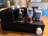
Hello, and let me introduce myself. My name's Mike and I have been following people's experiences on this forum for years. As with so many people, now my kids are (much) older, I have finally got around to using some of the tubes, chassis, iron and components that I've been stashing away for the last 20 years and have restarted my DIY audio journey 🙂
I decided (as I find myself in the process of evolving/swapping out DIY speakers and have only one completed at the moment) to start with a pair of mono 1626, or Darling derivatives.
So I designed the power supply (using PSUD2) to have a HT voltage of 266v under the 37mA load that the tubes will present to the supply. The input tube is a 12J5GT, to allow a single heater winding. The rectifier tube is a 5Y3GT (separate 5v filament winding), to get the voltage down to the level I need with my 520v CT PT without heating up too much resistance in the filtering network.
I decided to go with C(low)LCRCRC. Basically a 2uf cap followed by a 12H choke, then three 15uF motor run caps along with two 150 Ohm resistors and it did indeed work out to the voltage I was expecting when I built the amp into a steel Hammond chassis.
I powered the amp up and the two 12.6v heater tubes didn't light up, so I measured the heater V and found it to be zero because I had wired the two series secondary 6.3v windings out of phase. So, wiring corrected, I powered it up again and all was well. No hum to speak of either!
I measured all the voltages around the circuit (cathode bias V for each stage and plate V on the tubes etc.), and these were bang on what I intended. I started to listen to some music, it sounded great. But, after about twenty minutes I noticed a smell in the room and went over to check out the amp and noticed smoke coming from the power transformer! I shut the amp down and disconnected and removed the transformer and put it outside overnight to get rid of the smell (R-Core PT so lots of plastic tape). When I came to check it out in the morning I discovered that the insulation was melted and burnt on the secondary, and I'm wondering if this is because of the fact that I wired the heater windings out of phase and ran the amp to test voltages for maybe 10 mins?
I had in my stash another similar transformer with a higher secondary voltage (0-360v x 2 windings @100mA) and also 5v/2x6.3v windings, same mounting hole spacing - woohoo! So I figured I'd modify the power supply by removing the first cap and making it choke loaded (Hammond 193 series) to get the volts down to the same level as using the original PT. I removed the second 150 Ohm resister, replacing it with a 680 Ohm 2W type, which gave the same B+ voltage in PSUD2 as the original.
When I powered this up I got more 50Hz hum than with the cap input design and to my surprise the B+ voltage had dropped to 209 volts out of the power supply, so an overall plate V of about 180 on the 1626 and 200 on the 12j5. The amp works, but obviously not so loud (thinner sound as well) and there is hum in the background - sounds like 50Hz, although not audible from the listening position.
I did add the 2uf cap back in again and that pushed the HT V back to 266, but still the hum. So what I have now is a 720v CT 2uF cap input supply giving out the same voltage after filtering (with a 680 Ohm final filter resister that drops about 20v) as my original PT secondary of 520v CT - I've lost a hundred volts in the same circuit by swapping out the transformer.
The difference between the two transformers is that the original had a 200mA rating on the HT secondary. The replacement's rating is 100mA for 360v. Could that account for the 100v sag? I don't think so as the load is only 37mA total on the HT - 28mA on the 1626 and 9mA on the 12j5GT.
The drop in voltage using choke loading was even more pronounced. Is there some problem that I introduced into the circuit when I changed to choke input? The PIV of the 5Y3 wasn't exceeded - PSUD said 1000v and the 5y3 is rated to 1400. The motor run caps are rated 440v ac, which would be fine for 600v DC? Could the one following the choke have been damaged because when I changed to choke input the voltage waveform in that position was more like an AC waveform, and PSUD said it was 550v in amplitude? I couldn't measure it as my DVM is only rated for 500v ac.
One thing I did notice is that when I removed the 1626, the power supply output went up to 309v, so could that indicate a load intolerance in the PT? It's only supplying 28mA more! I also replaced all three tubes with others in my stash just in case it was a bad tube, but no joy. I measured the ac voltage across the 5Y3 filament and it measured only 4v, would that effect the emission of the tube bad enough to make it unable to support a 37mA load? Maybe it's just another bad PT? Coincidence? These were both bought from Ali Express from China? Has anyone had bad experience with chinese transformers bought directly?
The long and the short of it is I will purchase a traditional shrouded EI power transformer to replace the original and not use the higher v R-Core I installed for testing as I don't trust that it's any good given the drop in volts. It seems like very poor regulation to me? Or maybe it's faulty? I have scrupulously checked out the wiring for faults and can't see any reason to believe there's something in the output stage to load it unduly - the cathode bias voltage remains as designed so it can't be drawing an excess of current.
Am I missing something here? Any ideas/help would be most greatly appreciated 🙂
Regds,
Mike
Attachments
Hi
Very nice build.
Do you have a schematic of the amp ? If possible please show the dc voltage on every component in the power supply section.
If it was me, i would add some extra capacitors across these 15uF, just to verify if the B+ remains more stable.
Having the part numbers or a link to see the specs sheet of the original vs new power transformers would help.
BR
Eric
mikw st......PSUDII demands that you put dc resistance of PT secondary end to end for proper simulation.
1. If filter caps are leaking --please check
2. If PT gets very hot after 30mins use that you can't touch it for 3-5 seconds then it is
overloaded.
3. 100ma AC rating is ok for 37ma Dc load but you are ignoring the heater loads.
Please do as suggested and comeback to us ASAP we will fix it together no problem at all.
Regards
Please don't add any more capacitor in parallel to the existing ones right now it will make trouble shooting/finding faulty component more difficult. I think PT core structure has no major role here.
This is a clear case of PT overloading and it may happen due to :
1. leaky capacitor including filter caps and cathode bypass caps
2. faulty resistors or mislabeled resistors viz. level is 10K but its actually 5K
3. faulty tubes
4. bad PT (I doubt it though)
5. leaky PCB if you use it. etc
Regards
This is a clear case of PT overloading and it may happen due to :
1. leaky capacitor including filter caps and cathode bypass caps
2. faulty resistors or mislabeled resistors viz. level is 10K but its actually 5K
3. faulty tubes
4. bad PT (I doubt it though)
5. leaky PCB if you use it. etc
Regards
4 volt instead of 5 volt for 5y3 is definitely bad. What is the PT current rating for this.
Regards
Regards
These big old tfmr's like your second one weren't designed for amps, I have a massive tfmr, 330v 0 330v but only rated at 60mA. For comfortable running make that 70% of that. I've found the higher the HT secondaries the lower the current capability of most "scrap bin" tfmr's.
With any newly built power supply monitor the iron temperature for a good hour before use. Then soak test the amp for 24 hours running at 1/4 power say.
Andy.
With any newly built power supply monitor the iron temperature for a good hour before use. Then soak test the amp for 24 hours running at 1/4 power say.
Andy.
milkw st is using a1 se circuit, no use running it at 1/4 power i think. Your huge PT is only 60ma because the P and S is made of fine magnet wire that will yield high noise filtration/regulation. That does not mean it is not good for its purpose. Most of the PTs from old days (from reputable manufacturers) are excellent build quality.
Lets respect our past manufacturers/builders.
Lets respect our past manufacturers/builders.
1/4 volume/power in a soak test, not all the time.milkw st is using a1 se circuit, no use running it at 1/4 power i think.
What I was trying to get at regarding old tfmrs with higher than normal HT/B+ secondary voltage is that in my experience a lot of them do not have enough current capability for a power amplifier, preamp yes. I don't think it's a good idea if your running a tfmr at 100% of it's capability all of the time, no matter how well built, I wasn't dissing vintage tfmr manufacturers or tfmr's, though there were a lot of cheaply made border line tfmrs made for valve amps, guitar amps particularly.
That doesn't explain why your first tfmr burnt out though, 200mA HT current should be more than enough. To calculate Vdrop through chokes measure the DC resistance, times result by amplifier current draw. Check current draw of actual amp to see if there's a fault, high AC ripple is a good quick test, an indicator of a potential fault downstream,
Andy.
Last edited:
Hi, they're not all that old and are modern R-core transformers. The higher voltage one that I used to replace the first is the same physical size and has two secondary windings 0-300-360-400v taps. I've used the 0 and 360v tap for both windings in series, so 720v CT with the centre tap grounded and the 5y3gt as a full wave rectifier... I guess another thing to check is that I wired them correctly. I'm pretty shure I did as if they were out of phase the two would cancel each other and heat up the transformer, but they are putting out volts and the transformer remains cool.
There is normal (what I would expect) volt drop across the filter network and the expected current draw from the tubes. The voltage drop seems to be coming from the 5y3gt. Could a low filament voltage do that?
There is normal (what I would expect) volt drop across the filter network and the expected current draw from the tubes. The voltage drop seems to be coming from the 5y3gt. Could a low filament voltage do that?
4 volt for 5y3 instead of 5 volt may cause output voltage drop-sorry no personal experience here.
Asked you before asking you again what is the current rating against 5 volt winding??
Regards
Asked you before asking you again what is the current rating against 5 volt winding??
Regards
The 5v winding is rated for 2A. I've been really rushed at work today so haven't thought about drawing a schematic, I will over the weekend as I should have more time.
The amp is two stage with 12j5gt input/driver tube, which is choke loaded with a 250H plate choke (1000 Ohm DCR). It's cathode biased for -9v (910 Ohm Rk) and bypassed with a 16v Blackgate 470uF electrolytic cap. The coupling cap is a 0.1uF polyprop film type and the 1626 has a 1000H grid choke, which is about 3K DCR. The O/P transformer is 8K:8 Ohm and Rk is 820 Ohm, bypassed with a 1000uF Elna Silmic electrolytic cap with a 50v rating.
N101N, yes the volt drop is far too high I think.
Last edited:
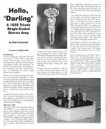

Thanks, I could never understand sharing a cathode resistor in the original. I wanted to keep the gain down as I only ever listen to my cd DAC which puts out a good 2v rms and the 12j5 seems excellent for that purpose (half a 12SN7).
I guess the original Darling was built to show what could be done on a tiny budget. I'm interested in getting the best out of the circuit hence the plate choke (from Sowter) and the grid choke. The plate choke may be a £150 "resistor", but it's much more than that and sounds amazing in some of the DHT amps I clipped together years ago when experimenting, but never built out.
When I manage to sort this amp out I have a #31DHT single ended stereo amp planned with a 1h6gt input/driver and battery filament supplies for a massive 380mW of power 🙂 My speakers are 100dB sensitive and I only tend to listen late at night so should be enough for me.
What’s cool w the Darling is that it can also be used with a different output tube and double the output power.
Just buy or make a 12B4A to 1626 tube socket adapter and you’re all set.
The 12B4A works well at the same bias as the 1626. Besides the need for the adapter no other changes are required. With the 12B4A you get 1.5W vs the regular 0.75W from the 1626.
BR
Eric
Just buy or make a 12B4A to 1626 tube socket adapter and you’re all set.
The 12B4A works well at the same bias as the 1626. Besides the need for the adapter no other changes are required. With the 12B4A you get 1.5W vs the regular 0.75W from the 1626.
BR
Eric
mikw st.........thanks. In your earlier earlier post you said 680r in your PS drops about 20 volt in that case your signal circuit is not over-loading the PS.
If your filter caps are okay, I think your power transformer is current wise over rated. However, you may try ss diode for time being. 1000H for grid choke is in little low side. You may try 470k resistor in that position. I use plate choke for driver tube in my 300b se amp and I like it very much. You should try 10, 10y, vt25, 801, 801A thoriated tungsten filament triode as output tube and that's best of the best.
Regards
N101N, yes the volt drop is far too high I think.
If so, go for the capacitor input filter.
You have a 5V 2A winding, that only puts out 4V into a 5Y3?
Something is very wrong.
Bad transformer.
Bad 5Y3.
Bad solder joint.
Bad tube socket.
Transformer rated input voltage, that is not the same as your power mains voltage.
The other transformer windings are very badly overloaded.
Etc.
Find the problem, or you may have another problem, major smoke.
Something is very wrong.
Bad transformer.
Bad 5Y3.
Bad solder joint.
Bad tube socket.
Transformer rated input voltage, that is not the same as your power mains voltage.
The other transformer windings are very badly overloaded.
Etc.
Find the problem, or you may have another problem, major smoke.
Thanks for your comments,
Eric. I've been using a 12b4a single ended amp for about the last 10 years and wanted to make a change. It's an all 9-pin amp with 6BW4 rectifier and parallelled 6463 input/driver, driving the 12b4a through an interstage transformer. It's not running very hot and puts out about a watt. It was inspired by the Gaby Levinson enjoythemusic.com article and uses the (then) popular Allied Electronics 6BW68HF interstage, which works fine when driven by the low impedance of the two 6463 sections parallelled together. I also ran it with the 12FV7, ECC99 (JJ), and 12BH7A, which all worked well but the 6463 sounds better so I rewired the socket for that.
Minhaj. I want to avoid SS and don't really want to keep the current transformer in circuit any longer than to test/troubleshoot. I'm going to go back to the 2uF cap input supply and will get an EI power transformer made up. My mistake re. the grid choke it's 3000H 🙂
N101N. You're probably right, the 193 Hammond choke probably isn't the best choice for choke input anyway although the volt drop seems excessive, but I will test that another day on the bench.
6A3sUMMER. Yes I think the transformer is bad. One of the things I noticed when I cut the original apart is that all the windings are insulated, where they are joined to other wire/windings, by what looks like paper and very thin. It doesn't inspire confidence. I'd rather go for an impregnated bobin where there's no room for movement. It's possibly where the hum comes from in the second unit? I tried two difference 5y3s so it's not the tube. There's one joint that doesn't look great, where the two secondary windings are connected together and grounded - I will redo that one and measure again. It's possible the socket is damaged from all the re soldering but looks ok. I'll measure it between the tabs. I measured the mains at 243v and the transformer is rated at 230v (115x2). The 12.6v winding (2x6.3 in series) is loaded with the two tubes and 0.55A total. It's rated for 2A. the 5v 2A winding has the 5y3 filament and that's it, no more secondaries.
- Home
- Amplifiers
- Tubes / Valves
- 1626 Darling monobloc - unexpectedly low B+ voltage when choke loaded