Hi guys - ok, the build is underway.
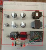
You are looking top down from the back of the proposed layout. Chassis is simple folded 1.6mm aluminium. Ends will be in solid rimu (podocarp timber). Width is to end up with a finished 43cm wide, 34cm deep (it goes on a 35cm deep shelf). The red outline is the perimeter of the top.
The chassis is 6.5cm high.
12SL7s on the left - they will have RCA inputs directly behind them in line with the speaker posts you can see. Sockets will mount directly to the chassis top plate - they drop in and are locked by a circlip.
The 1625s are on a 8cm centre grid - close, but not tight. Sockets will mount directly to the chassis top plate from underneath, on small stand-offs.
The iron is (screen top to bottom, rhs), 5.5h choke, 16.5h choke, PTX. OPTs sit behind the 1625s. All direct top mounting again except the PTX obviously drops through. An IEC power input socket with filter will sit behind the PTX
Underneath will be 2 x ccs circuits for the SL7's in ltp configuration; 4 x mosfet sf circuits between the ltp's and the 1625's.
Note all terminations are on the top of the chassis rather than the back - no depth to work with!
Cooling is via a mesh screen at hte back and radial drillings in the top plate around the tubes.
Straight power amp - no volume controls required.
Rip in guys...
Attachments
Hello,
Looks nice.
Perhaps you are braver than me. I would try the layout with clip leads to verify that there will be no induced hum or cross talk among and between the transformers and tubes with your proposed spacing.
1625’s are nice tubes top cap and all.
DT
All Just for fun!
Looks nice.
Perhaps you are braver than me. I would try the layout with clip leads to verify that there will be no induced hum or cross talk among and between the transformers and tubes with your proposed spacing.
1625’s are nice tubes top cap and all.
DT
All Just for fun!
Thanks DT - yeah, bit of a soft spot for top caps - last amp was EL36 (6CM5) with 6J7 front end...
I have the option of putting the smaller of the chokes as a through-chassis fitting. The layout is based around keeping the power iron at one end of the chassis, the input tubes at the other end.
Cheers
I have the option of putting the smaller of the chokes as a through-chassis fitting. The layout is based around keeping the power iron at one end of the chassis, the input tubes at the other end.
Cheers
Tranny orientation.
It looks like your power tranny is in the same orientation as the outputs.
I think the windings are effectively concentric.
Rotate the power tranny 90 degrees.
I would never use a drop through tranny as they tend to induce current into the chassis and if you use more than one chassis earth connection, then hum will be induced.
I prefer to join the mains to the chassis at the same point as the input connector and that is the only electrical connection to the chassis.
The other way is to join power earth to chassis and float the audio apart from one connection from the insulated input connector earth to chassis (preferably to the same point as the mains earth is connected next to the input connector).
Need to be a bit careful how the earth cabling is run, if it goes close to power transformer or chokes, it picks up current from induction.
You may be able to get a couple of covers and stand it up.
If you do, turn it round so it's 90 degrees to the output trannys.
Look at the ST70 layout, tou will see the way the windings go, the power is 90 rotated to the outputs.
Attachments
SSSHHHH
let's not let everyone know what a great audio tube the 1625 is. It is still a bargain.
I recently finished my single-ended 1625 with one 6sn7 and it competes with the KT88
single-ended my friend built at the same time except he used a 6sl7. Upon hearing mine with the 6sn7 he converted his over to 6sn7.
So my recomendation is drop the 12sl7 and go to a 12sn7or 6sn7, it allows a much greater current flow
John
thanks guys - marcus yeah, the earth scheme is subject to a LOT of thought at the momment - I stuffed up the last one I did and I'm determined to get it (mostly) right first time this time. Will definitely be floating the audio. Gotcha on the trannie orientation - thanks for that.
Fattie - yay for topcaps!!!! I'm using the 12sl7s because I have them and will be buffering them with a mosfet follower - they won't have to handle big current into the 1625 grids that way, and I keep the tube count down. Miles may cringe a little (or a lot) but I like the look and feel of minimal. Performance issues are dealt with under the top-plate and with sand.
Cheers!
It looks like your power tranny is in the same orientation as the outputs.
I think the windings are effectively concentric.
Could you elaborate on that? I don't see it 😕
I would say the windings of the OPT are vertical (i.e. on the picture) and the PT windings are horizontal?
yep and that may fix MOST of any cross-induction, but the best solution is, as marcus says, to reorient the ptx 90 degrees. THat way, the magnetic field from windings on the ptx are even less likely to cross the opt cores
yep and that may fix MOST of any cross-induction, but the best solution is, as marcus says, to reorient the ptx 90 degrees. THat way, the magnetic field from windings on the ptx are even less likely to cross the opt cores
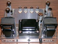
Well, if I may hijack this thread for this one question, I started on my amp and was about to drill the holes for the opt, now I'm unsure if I did it right, see pic:
An externally hosted image should be here but it was not working when we last tested it.
After reading these posts I was going to turn the opt's 90 degrees.
(After all that's how it was in the donor amp..)
nope - I think you are fine. THe ptx magnetic field is mainly propogated perpendicular to the long side of the ptx (so running from the bottom of your image to the top) so your opts are not in the main field. Just be careful with the wiring to your smoothing caps (brehind the ptx) as there will be high current pulses in htat wiring which MAY induce noise in the opts.
It a black art really... 🙂
It a black art really... 🙂
Okay, thank you for that!
The caps at the back are the last ones in the PS, but I was going to keep the wires on the left side anyway 😎
Now back to the original topic 😱
The caps at the back are the last ones in the PS, but I was going to keep the wires on the left side anyway 😎
Now back to the original topic 😱
"Fattie - yay for topcaps!!!! I'm using the 12sl7s because I have them and will be buffering them with a mosfet follower - they won't have to handle big current into the 1625 grids that way, and I keep the tube count down. Miles may cringe a little (or a lot) but I like the look and feel of minimal. Performance issues are dealt with under the top-plate and with sand."
understand the " I have them" approach our friend who designed my amp started with 6sn7's then put in some switched resistors and heater wires so now he can run 12 and 6 sn or sl 7's but after all his experimenting he went back to the 6sn7 at least in a single-ended application.
But that's half the fun of these projects, just don't make the mistake I did of too much voltage out of the power transformer, SE around 400v on the B+ for PP you could probably run 450v
john
Miniwatt your OPTs are on their 'sides' so the core orientation is vertical. Aardvarkash10 OPTs in the first diagram are on their ends, so the core orientation is horizontal.
The worst situation is to have the centre core of the windings co-linear, as is almost the case in Aardvarkash10s original layout drawing. (No offence meant, just a convenient picture to reference.) If they are at 90 degrees to each other, then the fields do not induce from one to another.
I make crossovers with very large air-cored inductors and if you turn one around while listening to the speaker, the sound difference is substantial. It is noticeable to even a casual listener.
regards,
Marcus.
Miles may cringe a little (or a lot) but I like the look and feel of minimal. Performance issues are dealt with under the top-plate and with sand.
Cheers!
Say what?
I have always admired your engineered approach Miles - and your tendancy to have plenty of current and gain in the front end is probably something I should take note of...
My style is perhaps a little too far the other way - expediency is my rule. Often at the expense of certainty of performance!
We don't have the easy access to parts you enjoy in the 48 so I have to improvise and use what is at hand - hence the low parts count and sand approach.
My style is perhaps a little too far the other way - expediency is my rule. Often at the expense of certainty of performance!
We don't have the easy access to parts you enjoy in the 48 so I have to improvise and use what is at hand - hence the low parts count and sand approach.
My style is perhaps a little too far the other way - expediency is my rule. Often at the expense of certainty of performance!
We don't have the easy access to parts you enjoy in the 48 so I have to improvise and use what is at hand - hence the low parts count and sand approach.
More than one way to skin that cat. You gotta use what ya gotta use. In the end, light 'em up and take a listen.
SSSHHHH
let's not let everyone know what a great audio tube the 1625 is. It is still a bargain.
Too late for that: the 1625 is a 12.6V 807. We already knew that. The most likely VTs used in such a design also have 12.6V versions as well.
Unfortunately it's one of those tubes where the sockets cost more than the tube itself. For a long time those sockets were very difficult to obtain.
John
John
Unfortunately it's one of those tubes where the sockets cost more than the tube itself. For a long time those sockets were very difficult to obtain.
John
Yes, and the current Chinese sockets seem to have reliability issues. I have had 2 that have had contacts fall apart before they were even used.
Gary
- Status
- Not open for further replies.
- Home
- Amplifiers
- Tubes / Valves
- 1625 pp amp layout - comments invited