As the title says - I narrowed my quest for the HV (950-1200VDC) tube rectifiers for an ongoing project using GM70/813/GU71 SE outputs.
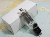
The tubes are electrically similar ,the 1616 sports an graphite anode and the 3B28 is xenon-filled.
What would you choose and why? Soundwise,tubes' lifespan?
Cheers!
The tubes are electrically similar ,the 1616 sports an graphite anode and the 3B28 is xenon-filled.
What would you choose and why? Soundwise,tubes' lifespan?
Cheers!
Last edited:
Super interesting question. I would prefer 3B28 over 866 with it's RF spluttering and it's pre-heating discomfort, but eventually went for 1616 despite it's voltage loss compared to the gas tubes. The DC is clean, the tubes as good as indestructible. and they look great. I run two pairs for over 25 years in my 211 amps, Xfrm 2.7 KV CT.

Both the 866 and 3b28 will need preheating. 3b28 might need a bit less than the 866 but still some preheating. Also they will need a choke input filter and some physical separation from the amplifier circuits.
I like the purple glow of the 3b28 over the 866. You just need to deal with the starting glitch at each cycle. Also last time I ran 3b28s I had kids in the room and did not want a possibility of mercury vapors so no 866s.
I like the purple glow of the 3b28 over the 866. You just need to deal with the starting glitch at each cycle. Also last time I ran 3b28s I had kids in the room and did not want a possibility of mercury vapors so no 866s.
Thanks guys for the comments.
@daqvin_carter : can you detail a bit about the preheating issue?I'm aware about the preheating of the mercury rectifiers but for gas rectifiers,it sounds futile as there's nothing to be vapourized...or it's about gas ionisation?
Some more questions: firstly,why a choke input?I intend to use a pair of 3B28 (or 1616,as a challenge) in a voltage doubler HT source,as seen in AN Ankoru,for a SE config using GK71 and/or 813/GU13 output tubes at @960...1150VDC.
Second,you said "You just need to deal with the starting glitch at each cycle." What did you mean by that? The output tube and all the others in the signal path are heating much faster than the rectifiers so the initial "thump" shouldn't be a problem....or am I wrong?
I have two datasheets for the 3b28. The TungSol datasheet says 'Minimum cathode heating time 5 seconds'. The RCA datasheet says 'Minimum heating time before anode voltage is applied 10 seconds'. I have started a power supply using the 3b28 and noticed an arc between plate and cathode when warmup time is not given. It will likely damage the tube to apply anode voltage without warmup time.
As far as startup glitch I am talking about each rectification cycle in this case.
The tube datasheets for the 3b28 lists a critical anode voltage of 50 volts. Normal anode voltage drop is 10 volts. In a power supply, the anode to cathode voltage must reach 50 volts before the tube starts conducting. The voltage will quickly drop to 10 volts with a very short transition. Dealing with the noise spikes will be easier with a choke input supply. A capacitor input or voltage doubler supply may have a problem with noise spikes on each cycle.
I can post the datasheets if needed.
Alot of useful,practical info here!Thank you daqvin_carter,I already saw the two different datasheets for the 3B28.Also, I'm already familiarized with the pre-heating issue in the mercury rectifiers' case but I wasn't aware of the importance of it when gas tubes are implied,your explanations are spot-on.Frankly,I'm a little afraid of the pre-heating thing followed by the HT switching on because I use Lowthers and their voice coils are rather delicate - not sure if they can take the "thump" of the HT kicking in.This is why I always used tube rectifiers with the slowest possible heating time (TV dumper diodes,for example).Aside of that - since there isn't a CT on the HT winding,where is the HT switch placed and what kind of switch can be use as to withstand those high voltages without sparking/arching?
On the other side - the use of a choke input changes the game's data - the HT secondary should have more windings for the same voltage at the output of the HT rect./filtration chain .Or, could it be used a small cap right before the choke ,for the voltage rising purpose?
On the other side - the use of a choke input changes the game's data - the HT secondary should have more windings for the same voltage at the output of the HT rect./filtration chain .Or, could it be used a small cap right before the choke ,for the voltage rising purpose?
It will be much easier to have a separate filament transformer for the rectifier filaments rather than attempting to switch the HT.
If you are able to get a power transformer with the right voltage to support a choke input supply it would be best to take that route over something with capacitor input or voltage doubler. You get much better power factor our of the choke input supply which can avoid noise and ripple. I am just typing knowing I have a pile of suitable transformers and chokes sitting in my basement.
As far as a startup thump it would take alot of output transformer bandwidth before that would be a problem. If it is a problem maybe the best option would be to have a small transformer to inject extra negative bias for the output tube that is only energized during the warmup period and would bleed off over maybe a 10 second period.
I never understood how a gas filled (xenon) rectifier works. Why doesn't the gas conduct both ways?As the title says - I narrowed my quest for the HV (950-1200VDC) tube rectifiers for an ongoing project using GM70/813/GU71 SE outputs.
The tubes are electrically similar ,the 1616 sports an graphite anode and the 3B28 is xenon-filled.
What would you choose and why? Soundwise,tubes' lifespan?
Cheers!
The gas acts more like a catalyst. You still have a cathode filament in all cases. You just have something reducing the on resistance.
OK,I understand that the separate filament XFMR is the way to go for the reasons you mentioned already.It shouldn't be a problem as my trusty local tech can wind (almost) anything I ask for.I already have some mains' XFMRs ready to use but they're slightly off (no separate fil.windings but on the same core with all the other fils. and no CT on the 5V windings).The choke input looks like a game challenge as I have to review the HT windings' specs according to calculations - today I began to look for calculations for this long-forgotten way of building a HT source. (BTW,any hints for a faster curve learning?)It will be much easier to have a separate filament transformer for the rectifier filaments rather than attempting to switch the HT.
If you are able to get a power transformer with the right voltage to support a choke input supply it would be best to take that route over something with capacitor input or voltage doubler. You get much better power factor our of the choke input supply which can avoid noise and ripple. I am just typing knowing I have a pile of suitable transformers and chokes sitting in my basement.
As far as a startup thump it would take alot of output transformer bandwidth before that would be a problem. If it is a problem maybe the best option would be to have a small transformer to inject extra negative bias for the output tube that is only energized during the warmup period and would bleed off over maybe a 10 second period.
The "thump" thing at the HT switch could be indeed solved as you described but I have to further study the idea as I don't have such an advanced education and knowledge.
Yes,thanks for the suggestion! (drool) 🙂Food for thought. 836 (2.5V 5A - 5kv)
I don't have these but I see they can be found on eBay...great alternative!
Slightly off-topic:
I just remembered I have a pretty hefty reserve (12pcs. or so) of the 3B24 tubes.These are the little "sisters" of the 3B28/3B29,of course handling less current but looking at the specs, they have a weird build detail,namely the filaments are 5V with a central tap.Never saw such a rectifier filament.As my existing XFMR's have 4 x 5VAC/5A (but no CT),may I use the 3B24's filaments' CT? ...in a Graetz bridge config followed by a CLC?Current-wise,they should cover the 130-150mA area for a SE w/813 and drivers.
I just remembered I have a pretty hefty reserve (12pcs. or so) of the 3B24 tubes.These are the little "sisters" of the 3B28/3B29,of course handling less current but looking at the specs, they have a weird build detail,namely the filaments are 5V with a central tap.Never saw such a rectifier filament.As my existing XFMR's have 4 x 5VAC/5A (but no CT),may I use the 3B24's filaments' CT? ...in a Graetz bridge config followed by a CLC?Current-wise,they should cover the 130-150mA area for a SE w/813 and drivers.
Perhaps best to spend more time locating and reading vintage books on mercury and gas rectifiers, such as Electronics Engineer's Reference Book edited by Turner which has a relevant section Electron Valves and Tubes. Google and key words can be your friend.
Also perhaps read the datasheets again and appreciate what each limit/comment means. You won't find capacitor-input filtering, so best not to go down that path. You will need to become very aware of choke input filter powering, and that needs as much effort in locating references and reading as well.
Hopefully you will then appreciate what is meant by arc-back, and ion bombardment damage to the cathode, and choke critical current, and how to design to meet datasheet peak cathode current, and even why the datasheets refer to the 'phase' of filament operation.
What you may not find are technical discussions and modern insight into the issue of ignition voltage, and how that causes a transient disturbance of the voltage drop across the diode, and how that then interacts with secondary winding leakage inductance, and has the opportunity to dwarf diode related disturbances that have sent many running after exotic SiC and soft-recovery solid-state diode devices.
You have picked quite a technically challenging project imho.
3b24 looks to be just a vaccuum rectifier without any sort of gas. More suited for a 5KV supply than 1KV. You would probably need to use four 3b24s to run a pair of 813s SE as far as plate voltage.
Also what are your plans for the amplifier side as far as plate current requirements? Have a schematic and operating points for the output stage?
Might just make it easier to
Also what are your plans for the amplifier side as far as plate current requirements? Have a schematic and operating points for the output stage?
Might just make it easier to
@ daqvin_carter I'm aware that the 3B24 is a vacuum,not xenon-filled tube.I was only implying that the're the "little sisters" because of the "3B..." mark,nothing else.Also,they have a 5V CT filament and heating really fast (specs indicate 2 secs. !) so it looks like the pre-heating issue is futile (please correct me if I'm wrong).
As far as my intention is to build monoblocks,I was thinking of use a full bridge of 3B24 per channel ,just for the output tube's HT supply so four of 3B24 might cover the needed current.Projections are centered on a SE 813 or GK-71 in triode mode,B+ of around 950-1150VDC @80-100mA per tube.The 1616 and xenon-filled 3B28 are next candidates (in a voltage doubler,of course - two retifiers per monoblock) only if the 3B24's don't deliver as hoped.As for the amp's config,the Millett's 12HG7/12GN7A suggested drivers are an appealing choice,both technically and for the sake of simplicity.However,the driver thing is a development subject as I have other candidates in mind (EL12 Spez. or even E2D ,both in triode mode,preceeded by some small tube w/ high transconductance ).The input and the driver,whatever they'll be,are of no concern because they'll get the "juice" from a separate HT section.
At the end of the rant - can I use the 3B24's filaments' CT,in absence of a "real" CT of each 5VAC XFMR windings?
Thank you again for all coments!
You have to look at the on resistance of the 3b24. It is about 1500 ohms. Rectifier losses would be fairly large. The 3b24 is made for higher voltages than you need.
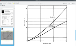
I was a little off on my assesment that plate resistance was a little lower at 100 volts. Flatter horizontally means higher resistance.
- Home
- Amplifiers
- Tubes / Valves
- 1616 or 3B28 HV rectifiers?