hi Eva, thank you for the infos and valuable comments, i m happy to find out that i have made the right choice , sorry for the typing mistake, again thanks,

If the freewheeling diode before the inductor reduces ringing, then there is probably some room for improvement in the layout of the windings of the main transformer. How did you wind it?
The two secondaries should be wound bifilar, preferably in one layer. The primary should be split in two halves, one layer each, and the secondary layer should be sandwitched between the two primary layers. The right amount and gauge of magnet wires should be chosen to get a good filling of the width of the coil former, without gaps between wires in the middle.
Note that if you change the rectification scheme into full bridge, you may be able to use lower voltage diodes which usually perform better.
Hola EVA,
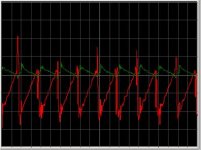
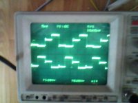
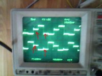
You are right as always. I will try with bridge rectifier. But I think that the close values of the primary and secondary windings cause hard sub harmonics in some load condition. On ocasions I see different ringing at odd and even pulses after the diodes and before the inductor. The current sense amplifier is trying to compensate this. With RC between hot secondary (without RC over the diodes) the pulses go in equilibrium, but the first sine becomes greater than half rectified pulse. Any way, the ps is stable, no heat.
My transformer is wery tightened, but consists of one layer primary and bifilar secondary in two layers. I will try bifilar secondary between bifilar primary, just for comparison and then go to bridge rectifier.
In this topology the secondaries should be perfectly matched (same resistance and leakage inductance), but it's just easier to use a single secondary and full bridge rectification (no more matching problems). Mismatched push-pull secondaries will usually result in suharmonic modes.
Sandwitched windings (1/2 pir - sec - 1/2 pri) will half leakage inductance. The primary halves should be wired in series.
Sandwitched windings (1/2 pir - sec - 1/2 pri) will half leakage inductance. The primary halves should be wired in series.
fob,
You can try to improve by using FREDFETs or adding anti-parallel diodes across the MOSFETs. Why don't you use an EE type pulse transformer?
You can try to improve by using FREDFETs or adding anti-parallel diodes across the MOSFETs. Why don't you use an EE type pulse transformer?
There should be no need for that in a standard full/half bridge, it's when you need to switch against a conducting diode like in a class D amp or motor drive inverter that is needed.
Tahmid said:Hi fob,
Your circuit seems ok, but you could try the following:
1. For quicker MOSFET gate discharge, add an anti-parallel signal diode across R2 (maybe a 1N4148).
2. At the 270-300v input, you should add an inductor of about 1mH before the 470uF capacitors to limit peak inrush current.
3. Increase the output inductor L1, from 150uH to about 400-500uH.
4. Since your switching frequency is 98kHz, the internal freewheel diode of the MOSFETs may be too slow and thus, cannot protect the MOSFETs from transients, while switching off. That's why, you can add anti-parallel ultrafast recovery diodes across each MOSFET of the bridge.
5. Since your switching frequency is high (98 kHz), you can remove R6 and R7 as your transistors are working in emitter-follower configuration. This will quicken the turn-off of the transistor.
Try these and observe and inform regarding the result. I think it will improve.
Thanks.
Eva said:
This is not very good advice.
2. Such an inductor is very bulky and not in any way required, and it won't do much about inrush current either. NTC inrush limiters alone are nice at low power levels. At higher powers they may be bypassed with a relay.
3. This results in an unneccesarily bulky inductor and actually worsens the problem because it causes the converter to work deeper into continuous conduction mode. 150uH is a good compromise because at 100Khz (200Khz clock) ripple current is in the 5A p-p range, which seems reasonable to me. The inductor should be able to handle at least 10.5A without saturating (8A + 5/2A). A 11A current limit (conveniently scaled by turns ratio and sensed at the primary) is recommended.
4. Wrong. Body diode turn on time is negligible, the problem is turning them off, but in such a circuit it should not be a problem either.
5. The 10 ohm resistors are there to protect the bases from damage due to overcurrent. The control IC can provide far more current than the bases can safely handle.
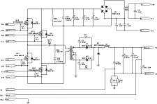
Four schottky clamping diodes are recommended to prevent both ends of the transformer from going higher than Vcc or lower than ground. They are not included in the SG3525A.
EVA is knowledgeable and we find her knowledge in many postings in this Forum. First, I thank her for her long comments regarding the suggestions of Tahmid, which has many points to think over.
While going through her comments, I could find that some of her observations are not appropriate- I will not use the word wrong as that is not a proper word I consider- as I find most of the suggestions of Tahmid is appropriate.
2. For a power supply of >1kw I think it is appropriate to use input inductor rather than fancy NTC for controlling inrush of current and the inductor should not be bulky as many Companies produce cores which are appropriate for this purpose and they are slim and small in shape.
3. It should not be bulky, just changing some turns and the suggestion of Tahmid is not bad considering the practical aspect- at least can be tried by increasing / decreasing some turns- since it is a test and trial effort by Fob.
4. Here, Tahmid wanted to mean, what you tried to mean and that is why your answer is same as Tahmid's suggestion. In most of the cases, it is a practice to add anti-parallel ultra fast recovery diodes across each MOSFET of the bridge when using > 50khz freq. as the circuit to be made should not be used for testing purpose all the time, rather for long duration and for that this sort of precaution is required.
5. 10 ohm resistor can be used but in FOB's circuit here it can be omitted also without any problem. Moreover, using resistor in transistors. like in this circuit, should be applied carefully as transistors can store charge and requires some time to discharge, so there is possibility of cross conduction of transistors and hence can disrupt the total action of pulse transformer.
I think Tahmid's suggestions are practical oriented and suggestions like these are helpful for trial and error circuits to find out valuable lessons and should not be discouraged.
placing a 1mh inductor after the mains rectifier (50/60hz) and before the 470uf filter caps is useless, 1mh nor smooth the dc nither limiting inrush current, moreover small size core will saturate and create some other problem,
Ok. If you think that the Inductor will saturate, donot use it. It is just a suggestion based on my practical work and little theoretical knowledge attained from different smps books. I used it in my circuit and working fine and so I find it useful not useless. I will consider your comment with seriousness and will further study and consult the theoretical books.
However, thanks for your comment and please let me know basing what calculation you have made such comment and what type of core you have considered which will be saturate as different companies produce different types of cut and uncut cores for inductors with different types of permeability and flux density, which are the main criteria for energy handling criteria for cores for inductors, not the size only. Hope, you will clear it in detail so that I can enlight my knowledge with your suggestion if I found your calculation is valid and logical.
However, thanks for your comment and please let me know basing what calculation you have made such comment and what type of core you have considered which will be saturate as different companies produce different types of cut and uncut cores for inductors with different types of permeability and flux density, which are the main criteria for energy handling criteria for cores for inductors, not the size only. Hope, you will clear it in detail so that I can enlight my knowledge with your suggestion if I found your calculation is valid and logical.
May be we must start another tread for main filters, rectifiers inrush limiters and others inputs.
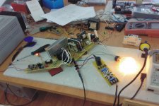
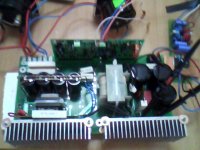
So, it doesn't matter if I have 10 or 100 ohms resistors before the complement folower. The problem is average current mode controll with non ZVSw bridge and allmost 1:1 transformer. This brings very nonpredictive rings. But with proper RC dampfers its working fine. I am going to buld boards and all the mechanical stuff.
So, it doesn't matter if I have 10 or 100 ohms resistors before the complement folower. The problem is average current mode controll with non ZVSw bridge and allmost 1:1 transformer. This brings very nonpredictive rings. But with proper RC dampfers its working fine. I am going to buld boards and all the mechanical stuff.
Attachments
After a long period of experimentation I gave up on using average current mode with transformers, now I only use it in straight buck, boost and class D converters, where it works very well.
Consider peak current mode with sensing on the primary side, you can remove the coupling capacitor that way (and say goodbye to subharmonics). Some slope compensation would be required too.
Forget the turns ratio of the transformer, it's *not* in any way related to the problem.
Consider peak current mode with sensing on the primary side, you can remove the coupling capacitor that way (and say goodbye to subharmonics). Some slope compensation would be required too.
Forget the turns ratio of the transformer, it's *not* in any way related to the problem.
thanks for the sandwich advice eva.
very good idea, now, i just have to speak about it with the manufacturer.
about the clamping diodes before mosfet drivers primary, it is stronglly recommended with everything, including an external synthesizer like the tecktronics i use.
i tryed in various configurations, and it appears that without these diodes, the pulses are full of harmonics and resonance.
but it create another problem, the revovery of the diodes will induce a little HF pulse.
the critical component in a full bridge seems to be only the rectifier diode on secondary.
use very very fast recovery diodes, with very low capacitance, a common mode inductor and capa in a double PI configuration filter, and it will reduce efficientlly the HF on output but need a big place on PCB.
Do you mean these parts?
When all transistors are off voltage over transformer will be 0V if in continous mode. But the common mode voltage on the primary will not be very defined and what it ends up at will probably depend on the order and delays when the transistors turn off.
When all transistors are off voltage over transformer will be 0V if in continous mode. But the common mode voltage on the primary will not be very defined and what it ends up at will probably depend on the order and delays when the transistors turn off.
Attachments
- Status
- Not open for further replies.
- Home
- Amplifiers
- Power Supplies
- 160v/8a