This is only indirectly an audio project but definately a tube one.
I have aquired an old WWII radar display tube, VCR97, which I would like to light up and use as a simple scope. For details see here http://www.tubecollector.org/vcr97.htm
Yes I'm sure there are easier and cheaper ways to aquire a scope but this is a piece of history that I should like to see working in some form.
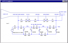
Now I could build a voltage doubler chain for a 1600v HT supply from parts I have immidiately available, using two 9v toroidal transformers back to back for mains isolation. See attached image.
Before I proceed to create a bomb, burn the house down or just vapourize myself I would like to ask a few questions here.
Those caps need to handle 660v. I am proposing to use two 400v rated caps in series in each position as shown. Is this safe ? Will they really share the volts or is there some catastophic failure mode here? Looks good in my simulations but that only maths not physics.
I have shown the tube's heater tied to the cathode at -1600v. Is this necessary and what kind of transformer would provide 4v with the required degree of insulation ?
On the other hand is there a simpler/cheaper/smaller/better way to get the HT at a couple of milliamps ?
I have read through the safety thread but still welcome advice/warning re: 1600v which I must say makes me nervous. I intend to build all this into a metal box for piece of mind.
Thanks all.
I have aquired an old WWII radar display tube, VCR97, which I would like to light up and use as a simple scope. For details see here http://www.tubecollector.org/vcr97.htm
Yes I'm sure there are easier and cheaper ways to aquire a scope but this is a piece of history that I should like to see working in some form.
Now I could build a voltage doubler chain for a 1600v HT supply from parts I have immidiately available, using two 9v toroidal transformers back to back for mains isolation. See attached image.
Before I proceed to create a bomb, burn the house down or just vapourize myself I would like to ask a few questions here.
Those caps need to handle 660v. I am proposing to use two 400v rated caps in series in each position as shown. Is this safe ? Will they really share the volts or is there some catastophic failure mode here? Looks good in my simulations but that only maths not physics.
I have shown the tube's heater tied to the cathode at -1600v. Is this necessary and what kind of transformer would provide 4v with the required degree of insulation ?
On the other hand is there a simpler/cheaper/smaller/better way to get the HT at a couple of milliamps ?
I have read through the safety thread but still welcome advice/warning re: 1600v which I must say makes me nervous. I intend to build all this into a metal box for piece of mind.
Thanks all.
Attachments
Woah! You don't need that much cap on a CRT. Each unit being maximum 4.7uF will do fine and in most cases, 1uF or less. You can also multiply each R by a factor of 10 🙂
Nice score with the CRT, BTW 😀
Nice score with the CRT, BTW 😀
Good grief! A CRT hardly draws any current! You certainly don't need to use 100uF. Read the data sheet for the CRT and I expect you will find that it needs only a milliamp or two. 1uF is probably quite enough for your voltage muliplier, allowing you to use proper plastic capacitors of an appropriate voltage rating. I suggest you have a look at some oscilloscope circuit diagrams...
Thanks EC8010 and Geek, you may have saved me a lot of grief.
However there was method in my madness:
My little project was inspired by the X-Y CRT indicator project of Frank Huges http://web.telia.com/~u43200663/inst/vcr97-0.htm. This is where the values of the HT divider chain resistors come from. With those we have about 1.7ma through the chain alone. Though he does have very small capacitor values on his voltage doubler.
The voltage doubler is adapted from one used to drive a photopultiplier tube by J. B. Calvert in his excellent practical electronics tutorial http://www.du.edu/~etuttle/electron/elect41.htm. Which I assummed would have similar current draw requirements. Notice the huge electrolytics. Problem is I need to handle the European mains voltage not the 110 volts he has and I need 600v more output. Hence going crazy with the caps.
My simulation with 10 times the Rs and 1uF caps shows me 170uA in the chain and a ripple of only 20v. I happen to have some 1uF/1000v caps around so I will try with that which also means I can use some smaller toriods I have.
There is still a question of isolation of the heater transformer that worries me. For now I'll light it up briefly with a battery.
Yes some scope schematics would be nice to see. Can't seem to find many on the net. Only Franks indicator, a Heathkit schematic that is to small to read and the best one here http://members.tripod.com/michaelgellis/scope.html If anyone has some links that would be great.
Thank you again.
You should use smaller capacitors and bigger resistors. A cascaded multiplier will also work, but there should be some other options, too. You might be able to find a module that does what you need without any fuss. I would look at the little HT supplies for energizing parts of copy machines and laser printers. maybe you can also play with rectifying the output of one of those small cheap cold cathode light inverters - I have this cheap car ionizer that works like this and emits a faint ozone smell (better than the usual "Caravan Musk" or "canned new car smell").
You should be able to find plenty of schematics for old equipment from the Boat Anchor Manual Archive. This is an archive for the manuals/schematics from old tubed and early SS gear, most of it is ham related or pertaining to kits. There are also some HiFi things in there. I would look at heathkit, tektronics, HP, and Eico. I typically use the main BAMA page to find what I am looking for, and once I have the file name, I use the (much faster, but without file descriptions) BAMA mirror server.
I would suggest that you go to a hamfest and pick up a fe old 'scopes and use them for spare parts or retrofit in this CRT. I would recommend getting a good and inexpensive used scope for general everyday use since it is difficult to make a omemade scope that works well for everyday usage.
I did take an old 14" SVGA monitor, disconnect the deflection coils,and connect them to the amp board from a set of crappy computer speakers (0.75 watts RMS per channel. some 16 pin DIP chip with a heatsink. at least it was honest 🙂 ). Right went to thevertical coil, and left went to the horizontal coil. it looked very cool, and you could easily differentiate between "mono" and stereo passages. dialogue and bass would simply extend a diagonal line. silence was a dot in the center. and any stereo content would either make the diagonal line fuzzy, or even make it go into all kinds of odd figure 8s and stuff. quite interesting. I called it AVDiS - Audio Visualization DIsplay System .
One simple way of achieving your heater supply with the required isolation is to wind an overwinding onto a toroid. In terms of current, you don't need a very large toroid (25VA would be easily enough) but a slightly larger toroid will make the job easier. Wind a few turns on with ordinary PVC-covered wire and measure the voltage to find out how many turns you need. Once you know how many turns, you can wind your secondary with EHT wire. EHT wire is the stuff used to go the the final anode of a television tube and will withstand 15kV - easily enough for what you need. It's quite large diameter, and that's why you want a large toroid so that it has a big enough hole to pass all those turns through. Another possibility is to use video co-ax with the outer PVC sleeve and braid stripped off.
It's quite possible that thinner insulation would do the job, but as you don't have a means of testing how safe your construction is, you have to over-engineer...
It's quite possible that thinner insulation would do the job, but as you don't have a means of testing how safe your construction is, you have to over-engineer...
I did think about the phosphor persistance, it must compare with TV tubes as young guys were building TVs with these tubes after WWII.
Perhaps I did not make my motivation clear in my original post but the idea here is not to build a scope on the cheap, I've contemplated that before and the cost/effort required has never looked good.
Rather I see this tube as historical artifact. It was one of the first tubes built for airbourne radar during WWII. It is huge, it's face is round and not very flat I think it's a beautiful thing. So I'd like to see it mounted in something classy, museum style, with a few simple controls and a way to view its internals. The deflector plates show cleary through the neck. And it has to light up and show something simple.
Sadly I have no idea how the original displayed radar images looked or I would try to simulate that. This calls for further research.
It's also a little nostalgic for me as my first ever engineering position was with the Marconi Radar Company in 1980, although tubes were substantially bigger by then.
If it is useable as a scope in anyway at all that is a bonus🙂
Thanks guys for your suggestions so far.
I will keep a look out for scrap HT modules. but I have enough parts to get on with just now.
The Boat Anchor Archive looks like it may be very helpful in future.
As an Englishman I sometimes miss the RSGB Ham rallies back home. Just now I'm resident in Finland and the last Ham fest I attended here was very small scale with little "boat anchor" exchange going on. Seems the Fins don't have a habbit to keep old stuff hanging around for years. Or perhaps the population is not big enough to support the activity we are used to.
That idea re: the hand made toriodal for the heater sounds promising. I need to go hunting for some high voltage cable anyway.
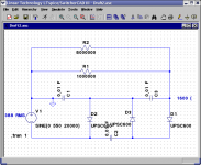
I had the same problem five years ago when I came across an old o'scope CRT. I used this to build a project that simply sent the left and right channels of a stereo output to the deflection plates to draw random squiggles on the screen, sort of a light show. For that, I used a variation on this power supply. With the values shown, the operating frequency is 14KHz. I used 2N3055s for the drive, since these weren't all that much more expensive than the 2N3053s I originally intended to use. The latter could be used very well, however, the beefier 2N3055's run well below their max ratings.
The transformer was a hand-wound job using the core from a TV horizontal deflection xfmr. Since this is a ferrite core, it doesn't have a decent enough saturation break for a Royer. With the values shown, the AC output is 1150V (measured) and works into a Walton - Cockroft tripler to 3000V(DC). Coupling coefficient is 80% (measured).
For the W - C, I used 10KV high voltage diodes, and 0.01uF filter capacitors (0.003uF total filter capacitance). The average DC current is 5.0mA (nominal) to provide up to 1.0mA of DC for the CRT (current limited). This doesn't take up nearly the space that a power line frequency xfmr would need, and the high operating frequency makes flicker a non-issue.
Note: Use #22 (AWG) to wind the primary. Also, be careful with this as it does put out the stated voltage, and can give you quite a shock.
Miles Prower said:I had the same problem five years ago when I came across an old o'scope CRT. I used this to build a project that simply sent the left and right channels of a stereo output to the deflection plates to draw random squiggles on the screen, sort of a light show.
"Random squiggles?" An audio vectorscope (yes, that's the professional name for it) is actually very useful. It quickly indicates if one channel's polarity has been inverted (easily done in a balanced audio environment). It can be used to aid setting up cartridge yaw (adjust for minimum in phase signal on vertical modulation). It reveals synthesised stereo (the balls of wool become suspiciously circular). I expect there are other serious uses, but the main one is... ...it's pretty.
I keep meaning to incorporate a CRT Lissajous display plus A&B stereo PPM into my electronics...
Miles Prower - It is possible you have saved my life.
Of course, crank up the frequency and the size of the capacitors goes way down, ripple is reduced, stored energy is reduced. Probability of surviving any misshaps is increased 🙂
Now I do worry about ripple, not because of flicker but because the beam deflection is dependent on anode voltage. I estimate that a 100v p-p ripple results in about 1.5mm spot movement which would make any display seem more fuzzy than it need to. No idea what the spot size may actually be in this old tube though.
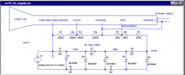
Working my the design backwards from my available high voltage capacitors, 0.1uF or 0.01uF at 1500v I came to the attached voltage doubler which run at 20KHz provides 1600v with a ripple of only 26v p-p. The 8M resistor there represent the load of the actual beam current, 200uA. The 1M is whatever voltage divider chain I may need.
I already built a circuit very much like yours to get a 300v tube supply from batteries so I should have thought of this before. The fly in the ointment for me is the transformer, I have no experience of winding these and no one around here has any ferrite rods, only toroids. How would I get 1000 turns onto a toroidal ferrite core ?
To keep all this on topic for an audio forum, any one who asks will now be told I'm building an "audio vectorscope". That is no doubt the first inputs it will see anyway 🙂
Of course, crank up the frequency and the size of the capacitors goes way down, ripple is reduced, stored energy is reduced. Probability of surviving any misshaps is increased 🙂
Now I do worry about ripple, not because of flicker but because the beam deflection is dependent on anode voltage. I estimate that a 100v p-p ripple results in about 1.5mm spot movement which would make any display seem more fuzzy than it need to. No idea what the spot size may actually be in this old tube though.
Working my the design backwards from my available high voltage capacitors, 0.1uF or 0.01uF at 1500v I came to the attached voltage doubler which run at 20KHz provides 1600v with a ripple of only 26v p-p. The 8M resistor there represent the load of the actual beam current, 200uA. The 1M is whatever voltage divider chain I may need.
I already built a circuit very much like yours to get a 300v tube supply from batteries so I should have thought of this before. The fly in the ointment for me is the transformer, I have no experience of winding these and no one around here has any ferrite rods, only toroids. How would I get 1000 turns onto a toroidal ferrite core ?
To keep all this on topic for an audio forum, any one who asks will now be told I'm building an "audio vectorscope". That is no doubt the first inputs it will see anyway 🙂
Attachments
- Status
- Not open for further replies.
- Home
- Amplifiers
- Tubes / Valves
- 1600v HT supply for scope.