Is there a better, quieter, more elegant way of developing +/- 15VDC from +/-75VDC rails??
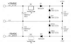
An amp i am working on uses this schematic to power the front end from the +/- rails. It works, but they used two 5 watt resistors piggybacked on top of each other without any sort of support to the PC board, or each other. and because this amp see's regular road use, the piggy backed resistors ended up breaking the solder connections causing the amp to fail.
this just seems like a brute force way to do this. and Most V-Regs like a 7815 etc cant handle that much on the input side.
If i calculated the power dissapation correctly, then there is about 5.5 watts going up in heat which was enough to discolor the resistor legs and board around them.
I thought of changing the resistors and zeners to develop +/- 30VDC then using regulators, but i thought there must be a better way to do this using a transistor as the pass device etc.
There is not enough room in the chassis to mount another transformer, but i can put a small PC board vertically inside next to the cap bank board.
Can anyone show me a schematic that i can adapt. and would there really be any benifit to going through the trouble??
Zc
Attachments
if you use a regulator you would need to mount it on a heatsink and as youve said you are limited on room as a small remedy in regard to heat try increasing the power rating of the pass resistors
Hi Zero Cool,
I hate, crappy cheap supplies. You may gain a lot from using a switching supply off the rails. A 555 timer set for a 30% duty cycle ( or there abouts), followed by some filtering and normal regulators would get you there. Use the 555 to drive transistors on the rails through optocouplers. You can use FETs or BJTs since this is low power.
I'm sure there are more elegant ways to do this, this is just to get you thinking.
-Chris
mastertech said:if you use a regulator you would need to mount it on a heatsink and as youve said you are limited on room as a small remedy in regard to heat try increasing the power rating of the pass resistors
If i remove the resistors and mount a PC board vertically, i could mount a pair of TO-220 devices on heat sinks. there is enough room for that but not for a transformer.
I dont know that i could build a switcher supply and make it quiet enough. i have no experiance building those.
I am going to dig through my old Audio Amatures and see if there is a V-Reg sam in there i could modify or something. if nothign else i will be changing the resistor setup to be more solid and road worthy.
Zc
Member
Joined 2002
jleaman said:What about using the Nelson Pass Zen regulator ?
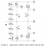
DUH! you know i never thought to look there! But look what i found, a simple easy circuit that looks like it will do the trick!
Now according to the text, the Zeners need to total about 4V higher then the desired output voltage. so, i should be able to just remove one of the 10V zeners per side for a total of 19.1V remaining minus the VGS of the mosfets should yield 15.1V thereabouts.
Now, will i need to change R1 & R2??? and i wonder what wattage those should be. I just so happen to have some of those mosfets on hand, but i think my front end is drawing only 100ma or so, so i may try and find some smaller mosfets to conserve space.
Zc
Attachments
Member
Joined 2002
I'm thinking about building a few of these regulators for some stuff at home i already have a board layout. : O )
Oh yeah, forgot the disclaimer...
The schematic show above is of course the property of Nelson Pass and is shown for reference and Education only etc etc. DONT STEAL THE DAMN THING AND CALL IT YOUR OWN OK!!! hahahahha
Zc
The schematic show above is of course the property of Nelson Pass and is shown for reference and Education only etc etc. DONT STEAL THE DAMN THING AND CALL IT YOUR OWN OK!!! hahahahha
Zc
Member
Joined 2002
Zero Cool said:Oh yeah, forgot the disclaimer...
The schematic show above is of course the property of Nelson Pass and is shown for reference and Education only etc etc. DONT STEAL THE DAMN THING AND CALL IT YOUR OWN OK!!! hahahahha
Zc
Yup im building mine for personal use not To sell : O ) He has great design's..
It may be crude but it works. If the trouble is the resistors cracking free, they need support. I often have to resolder them in Crate and Fender products for this reason. A line of silicone will hold them in place and seriously reduce the motion that causes the solder to fail. Or mount larger resistor to the chassis wall in clamps and run a couple wires. More complex circuitry is not always the best approach.
Apart from the switching option suggested by anatech, all the other options will produce the same, or more heat. You might get a better quality of power supply though.
I would just get some ali clad power resistors, and bolt them to the chassis somewhere near, then just conect up with flying leads.
Cheap and easy. 😉
I would just get some ali clad power resistors, and bolt them to the chassis somewhere near, then just conect up with flying leads.
Cheap and easy. 😉
The whole front end is powered off the +/-15VDC a preamp section and 2 parametric eq sections.
I am adding the vertical board anyway to the amp as there are no fuses on the B+/- anyway. if one channel should fail (which it did) there is nothing to protect the thing from totally destroying itself except the 10amp line fuse!!! So i am adding a board in there with fuses between the power supply and each amp board just to try and help save the thing a little bit should it ever fail again. at least try and save the PCB board and traces from burning up.
So i have a small amount of room in there between the fuse holders where i could put a regulator that uses TO-220 pass devices mounted on small heatsinks. OR, i may just use some larger resistors or maybe parallel several together to reduce the tempurature of each down a little bit. the total heat will be the same, but each one will run cooler.
But before i went that route, i thought i would explore what possibilitys are out there and the PASS regulator looks like it would do the trick nicely and fun to build and experiment with.
A small transformer really would be the best option. and im still looking to see if i can somehow squeeze one in there, but i think the regulation would actually be worse then. as there would be no regulation at all. i would have to add some regulators and a small trafo. but i could at least then use off the shelf 78xx devices.
BUT,... would that be better?
Zc
I´d definitely vote for the extra transformer.
You might fight a defective satellite-tuner or similar where you can find the right one or just buy a little 15VA which should be sufficient and easy to squeeze in somewhere!?
You might fight a defective satellite-tuner or similar where you can find the right one or just buy a little 15VA which should be sufficient and easy to squeeze in somewhere!?
Check out my website. A full design including board layout to do exactly what you need 🙂 www.readresearch.co.uk click on High Voltage PSU.
I'd vote for the transformer plus regulator IC's. Failing that, run the 555 at higher frequencies and it'll be clean. Say 10KHz~40KHz, filtering that isn't too hard.
There are more elegant designs out there. Possibly a module or all-in-one chip you can use.
Richie00boy's circuit has additional filtering which is good. I just don't like extra heat, like the original design.
-Chris
There are more elegant designs out there. Possibly a module or all-in-one chip you can use.
Richie00boy's circuit has additional filtering which is good. I just don't like extra heat, like the original design.
-Chris
Auxilliary supplies regulator
Hi all
Here's the schematic of the auxilliary supplies regulator I used on my PowerDAC1 digital amplifier. It runs off 75Vdc provided by the main SMPS converter, and outputs +3.3V, +5V, +12V, -12V, plus a floating +12V for hi-side gate drive powering of an external sync reg, all from a single switchmode, with quite reasonable cross regulation. It's a simple forward converter with a core reset winding and a coupled output inductor. TI has a plethora of app notes and design guides on coupled inductors. Max total output power is 30-35W and the transformer is an RM series coreset, as I recall.
All the circuitry associated with Q16 is for locking the switching frequency and may be omitted if not required. The regulator powers itself initially from the +75V through Q18, but once the +12V rail is up and running, it extracts power from this and D40/42 are backbiased. All unneeded rail output circuits can be omitted.
The circuit posted is not the latest version, as it doesn't have the -12V rail output, which I added later. I'll try to dig up the latest schematic as well as some transformer details and post these if there's any interest. In practice this it has worked well for 5 years, has low ripple and is robust towards secondary abuse.
Also it uses simple, cheap components.
JohnH
Attachments
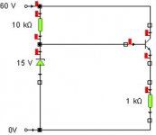
I looked in the power supply section of "Success in Electronics" and found what it calls an "emitter follower stabilizer".
It's a power transistor whose base voltage is controlled by a Zener diode. The output voltage is the Zener voltage minus the base voltage. Apart from the transistor and Zener diode, the circuit has two resistors.
It's a power transistor whose base voltage is controlled by a Zener diode. The output voltage is the Zener voltage minus the base voltage. Apart from the transistor and Zener diode, the circuit has two resistors.
Attachments
Tim: This circuit is OK provided your current drain from the +15V is very small. But it is simply a linear regulator, and if you were to draw, say 50mA to power a lot of op-amps in a preamp or something, the power transistor would dissipate 2.25W and would require a heatsink.
John
John
This is an old thread so I suppose that ZeroCool has already solved his problem. But anyway, I think that the smartest solution is to wrap two auxiliary 18V AC windings around the main toroid transformer (in case it's a toroid and it's not encapsulated).
This will provide about 27V DC max. to the front-end PSU so dissipation will be strongly reduced and IC regulators are suitable.
The SMPS is also a very smart solution, altough it has a great degree of complexity and uses additional space.
This will provide about 27V DC max. to the front-end PSU so dissipation will be strongly reduced and IC regulators are suitable.
The SMPS is also a very smart solution, altough it has a great degree of complexity and uses additional space.
- Status
- Not open for further replies.
- Home
- Amplifiers
- Power Supplies
- +/- 15VDC from +/-75Vdc Is there a better way?