
IIRC I once read on a French spoken (actually written) forum that someone came up with the idea to use such a waveguide for coupling a driver to a DIY radial horn. I don't know what happened to this idea afterwards.
I would say that the horizontal dispersion control of your waveguide would work as intended but I am not that sure about what is going to happen regarding the vertical dispersion control.
Regards
Charles
I would say that the horizontal dispersion control of your waveguide would work as intended but I am not that sure about what is going to happen regarding the vertical dispersion control.
Regards
Charles
IIRC I once read on a French spoken (actually written) forum that someone came up with the idea to use such a waveguide for coupling a driver to a DIY radial horn. I don't know what happened to this idea afterwards.
I would say that the horizontal dispersion control of your waveguide would work as intended but I am not that sure about what is going to happen regarding the vertical dispersion control.
Regards
Charles
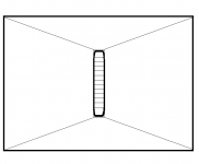
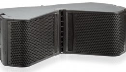
I wondered about the vertical. The JBL 2382A seems to be less complicated, with a wide open throat:
Attachments

You cannot modify it to have a wider vertical dispersion, that would require a complete redesign.
You cannot modify it to have a wider vertical dispersion, that would require a complete redesign.
Thank you!
You're on the right track, but why would you go this route?
1) There's going to be massive diffraction as you transition from the diffraction slot to the horn "bell"
2) 18Sound offers waveguides that will give you the pattern that you want, but are FEA optimized and well-thought-out.
1) There's going to be massive diffraction as you transition from the diffraction slot to the horn "bell"
2) 18Sound offers waveguides that will give you the pattern that you want, but are FEA optimized and well-thought-out.
You're on the right track, but why would you go this route?
1) There's going to be massive diffraction as you transition from the diffraction slot to the horn "bell"
2) 18Sound offers waveguides that will give you the pattern that you want, but are FEA optimized and well-thought-out.
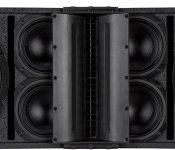
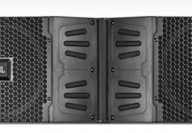
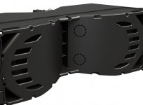
Partly because I thought that style of 140*x15* waveguide required the additional horn, but only based on looking at pictures of line array cabinets. They have the HF driver mounted inside the cabinet, with additional flare as part of the cabinet.
Attachments
Last edited:
I asked Eminence tech support about using a horn in front of their similar line array waveguide to lower the frequency from 1k to 800Hz. Here was his response:
"The angle of the wood defines the coverage pattern. The degree of coverage can be whatever you want. The depth of the horn needs to be at least a quarter wavelength of the lowest frequency, for 800Hz that will be about 5, maybe 6”. The mouth of the horn also has to be as large as the lowest frequency wavelength. For 800Hz, that’s about 1.4 feet. The perimeter of the mouth needs to be larger than this in order to maintain pattern control."
"The angle of the wood defines the coverage pattern. The degree of coverage can be whatever you want. The depth of the horn needs to be at least a quarter wavelength of the lowest frequency, for 800Hz that will be about 5, maybe 6”. The mouth of the horn also has to be as large as the lowest frequency wavelength. For 800Hz, that’s about 1.4 feet. The perimeter of the mouth needs to be larger than this in order to maintain pattern control."
- Status
- Not open for further replies.
- Home
- Loudspeakers
- Multi-Way
- 140x15* LA Waveguide modification to 100x50*