the amplifier's speaker output terminals.
The R+C at the amp's terminals completes the HF load that the amp needs to see and it also attenuates interference coming in through the speaker cables.
The Zobel alone does a very bad job of attenuating cable induced interference getting to the -IN input.
The Thiele improves on this significantly.
the Pi improves attenuation further still and seems not to interfere with sound quality since it is well separated from the amp output by the full Thiele Network.
the amplifier's speaker output terminals.
The R+C at the amp's terminals completes the HF load that the amp needs to see and it also attenuates interference coming in through the speaker cables.
The Zobel alone does a very bad job of attenuating cable induced interference getting to the -IN input.
The Thiele improves on this significantly.
the Pi improves attenuation further still and seems not to interfere with sound quality since it is well separated from the amp output by the full Thiele Network.
I am not familiar with Thiele network, how can it be implemented on this amp?
a Zobel R+C from amp output to amp power ground plus a L//R from the amp output to the amp's speaker terminals = Thiele Network.
Thiele also moves the Zobel from before the L//R to after the L//R
The values of the components change depending on speaker impedance, amplifier's required HF load and which Thiele Network is being implemented.
My idea of the Pi filter is combining the two optional Zobel locations either side of the L//R. I have seen this very occasionally in other designs. It was when I read Cherry's paper on the Thiele that I came to realise what I had seen and started experimenting with it.
BTW zobel typically 10 Ohm in series with 100nF in above schematic connects accross the speaker terminals. Remeber that in above example these are not extra capacitors, they are your reservoir caps.
Nico
Nico
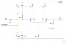
BTW R7 = R8 value should be low enough to swamp base current of input transistor, say twice to three times the base current.
Thanks Nico,
#44 is brilliant, we have seen it before on a headphone amp you did on my forum, and it gets around all the switch-on problems. However it does place the speaker lines at +70V wrt ground, which could be a problem in a PA/sound reinforcement scenario.
Thanks again for the input, Nico, much appreciated,
Hugh
Thanks Nico,
#44 is brilliant
Thanks again for the input, Nico, much appreciated,
Hugh
MegaDitto 🙂
Can the caps be 70V or need to be be the whole 140V ?
http://home.comcast.net/~mnjmiller/mosamp.gif
Attachments
Last edited:
Thanks Nico,
#44 is brilliant, we have seen it before on a headphone amp you did on my forum, and it gets around all the switch-on problems. However it does place the speaker lines at +70V wrt ground, which could be a problem in a PA/sound reinforcement scenario.
Thanks again for the input, Nico, much appreciated,
Hugh
Hi Hugh, would you agree that the output of the amp at steady state is at half supply and that the center of the caps are at half supply. Why would it be different for P/A use?
PA amps also uses a Push Pull output arrangement, this configuration will also work for a transformer. In fact it would work for any push pull amp regardless if it is single or split supply and ultimately protects the speaker agains DC regardless of the fault.
Nico
MegaDitto 🙂
Can the caps be 70V or need to be be the whole 140V ?
http://home.comcast.net/~mnjmiller/mosamp.gif
For Caps in series their voltages are added totgether, thus two 70V caps in series will be equivalent to a single 140V cap. However, two 1000 uF caps in series is 500 uF.
Nico
Nico, just a misunderstanding!
You are right; I simply mean that the two speaker wires at steady state would both be at 70V wrt ground, that is all.... this might be an issue in PA where lines are long and often exposed.
Hugh
You are right; I simply mean that the two speaker wires at steady state would both be at 70V wrt ground, that is all.... this might be an issue in PA where lines are long and often exposed.
Hugh
single 140V + NMOS + ... = Normal amplifier
... = output transformer, or
... = complex design, or
... = fast and precision bridge network., or
... = others
May be transformer is the simplest.
... = output transformer, or
... = complex design, or
... = fast and precision bridge network., or
... = others
May be transformer is the simplest.
Hi,
Single supply rail with zero thump using two series caps in the rail in stead of one. Why no thump, because capacitors are charged in series and juntion is at rail/2, there is no voltage developed over speaker.
Regards
Nico
Hi, First time that I have seen this arrangement and seems good. But for the proposed PSU I am going to use 30 pcs of 1200 uf/200v capacitors in parallel with a CLC form. so there will be no center tap point. Else, I would add 2 10,000 uf/75v in series then tap the speaker terminal on the center. Will this be okay?
With this will still need a DC protection?
You may try also something unusual, in such style:

Hi Wavebourn...
Nice class A amp...how many watts?
Maybe i can give a try later when this project is done...
any idea for this 140v Nmos amp?
Thanks
jun
Nice and simple amp using complimentary pair laterals Mosfets....little bit similar to Grandmos ProFet and zenquito's.
Will this work on 140v single rail?
Nice and simple amp using complimentary pair laterals Mosfets....little bit similar to Grandmos ProFet and zenquito's.
Will this work on 140v single rail?
I haven't done it but no reason why not ....
Does maybe have turn on --- off ? thump ?
But basically kicks a**
I haven't done it but no reason why not ....
Does maybe have turn on --- off ? thump ?
But basically kicks a**
It would need 4 pairs of outputs though to
robustly drive speakers.
- Status
- Not open for further replies.
- Home
- Amplifiers
- Solid State
- 140v single rail Nmos amp..