FOV spec
I think we don't see FOV specs for most lenses because it depends on the throw distance. But we could see a maximum field angle spec. Then you could calculate the maximum field of view at a certain LCD-to-lens distance.
But this assumes that a lens cuts off all the light beyond a particular angle. That is not true. Both duplets and triplets usually have an internal stop aperature to make the image illumination even from all angles specified in the performance requirements. (In most triplets, it is the smaller diameter negative lens in the middle.) Without the stop, the central part of the image would get more light than the edges, so it would be brighter.
The maximum field angle is the circle where the combination of the outer lens diameters, the mounting tube, and the internal stop begin to block some light. But light from beyond that circle will still make it through the lens. As you get farther from the circle, less light will get through so the image of those points will get dimmer. You won't even see the difference in brightness if only 10% of the light is blocked. So then were exactly is the boundary of the useful FOV?
Another useful question to think about: Are 17" LCD corners dim because they are beyond the useful FOV of the projection lens, or is the problem really with uneven illumination by the fresnels? If we assume a throw distance of 122 inches with a 450 mm fl lens, then the LCD-to-lens distance will be 526 mm. (This should give a 100" image.) The LCD half diagonal distance is 215.9 mm. By Pythagorean Theorum, the distance from the lens to the corner of the LCD is 569 mm. If we take the inverse sin of (215.9 / 569) we get 22.3 degrees. That is the half angle, so the full field angle is 44.6 degrees. Triplets generally work perfectly out to a 45 degree field angle. (By the most conservative definition of maximum field angle.) So it looks like all of the 17" LCD would be within the lens's FOV.
You can use the same method to calculate the required field angle for a 220 mm fl condensor fresnel. 215.9 mm half width with a 220 mm lamp-to-fresnel distance gives you a full field angle of 88.9 degrees! So maybe somebody with dim corners on their 17" LCD should try using a longer focal length condensor fresnel!
Squalish said:Rox, I direct you to this thread:
http://www.lumenlab.com/forums/index.php?showtopic=5230
His site has more info.
jeje, yes, i know him, is a very good friend of mine 😀, what he did is get the lens elements closer so the focal lengh increased and this way he could proyect from his 17" lcd. We believe the FOV value of the lens increased as well. His 135triplet "native" results are not very good. But is the few ones that have posted results. I believe the native FOV is not compatible AT A RASONABLE THROW.
Hi guy grothke, long time didn´t post to you 😀.
one of the repplys to one of the two 135 triplet sellers everibody knows when i asked about the FOV value was that the manufacturer told him it depens on the aplication. Actually i am not sure but i think it is not true. I think that the lens has a FOV value defined by construction just like the focal lengh (it is defined by construction and is independent to the aplication).
now, it is true that in some aplications (short throw cases) the needed fov could be smaller than the max fov of the lens. But i would say that the native fov from the 135 is poor for 17".
the fov of a common triplet you say it is 45 degrees, well, if i take my laser and bend it to the 80 triplet, the angle is much more than 45 degrees(i can reach 60degrees before the laser turns off). I´will do some test on it but have no 135 triplet.
lets see your math;
your 100" screen is 2meters wide moreless. I don´t know if it is a standar image but my friend diyeitor (first 17" diymaker from spain) has 2,5 m wide imagesize. he has a litle bit more throw than your example (so triplet is something closer to the tft). The fact is that his corners are black. He has moved the bulb front/back to see if it was the light the problem (it could be that the light cones were outside of the triplet but it was not the case, you know some OHP have a wheel to move the lamp position so ligh cones can be adjusted for each trhow?) so the conclusion was that with such a screen size the FOV was not sufficent.
I would like to see some results of your example (100") at 3M throw distance, and full screen 17" image source. Do you know where can i find some?
do you think manufacturers don´t know the FOV of their lens?
thanks for your atention, i use to have a very good time with you 😀
Hi Rox
I agree with the manufacturer: I am sure all lens manufacturers know the maximum useful field angle of their lenses, but the FOV of a triplet depends on what you are doing with it because FOV is the diameter of the circle on the object plane. With different throw distances, the object plane (the LCD) will be different distances from the lens. But what does remain constant is the field angle.
You saw that some part of your 80 mm diameter triplet would pass a laser beam at a 30 degree angle from the central axis. But I think that only a small portion of the lens would do that. Within the useful field, the same area of the lens (ie. square mm)will pass rays to the other side. As the source of those rays is moved around, different parts of the lenses may be used, but the total area remains the same. The maximum useful field angle is where a smaller area of the lens will pass rays. That will make the image progressivly dimmer past that angle.
Sorry, I can't run this test for you: I don't have a triplet. I have some DIY duplets with lower field angles and a Rodenstock tessar that has a larger field angle.
I think your friend with the 17" projector should take the projection lens out and put his eye (covered with very dark glasses or welding goggles) right where the lens goes. Then he should look at the corners of the LCD. I bet they are much dimmer than the center. That would prove the problem is with the condensor system instead of the projection lens. If that is the problem, then one solution is to change to a longer focal length condensor fresnel with matching spacing between the lamp and the condensor fresnel.
So i confussed the fov value with the field angle. I thought they where the same thing.
now my rearch will be to determine the field angle 😀.
when my friend had the triplet natively, he proyected from his 17"lcd as well. He did some test; with the backlight of the lcd, he just placed the triplet at the same position that would be for 2,5M wide image and 3,5M throw. (there was a dimm image but the corners where black as well)
when you use such image source, without field fresnell, like crt projectors people do, the light is not very effective since it it homnidirectional, but this test shows it is not the front fresnell focal lenght problem. He did what you are saying as well (looking trhow the triplet very close to look if he could see the corners of the lcd, and he told me that he couldn´t see them).
just let me check this, the max fov value for our aplication should be equal to the field angle?
I just havent seen results for 17" and don´t know why, i know lot of people started doing one. And the two only results i have seen where blackcornered.
thanks for you replys.
fov and field angle
Field Of View is the diameter of the circle in which a lens delivers 100% of the light. When you take a photograph with a large format lens (just like a projection lens but the light is going the other direction) the image will be focussed at one focal plane, some distance from the lens. If the object being photographed is at a far distance (like a landscape), then the focal plane will be the lens's focal length from the lens. Then the FOV will be the product of the maximum field angle and the focal length.
If the object being photographed is much closer (like a group protrait), then the focal plane will be farther away from the lens. The maximum field angle will stay the same, but the FOV will be larger since the cone of light spreads out over a greater distance. This is like an LCD projector: The FOV is larger because the LCD to lens distance is longer than the lens's focal length.
dim corners
There are several things that can cause dim corners in the screen image. Each one can be determined by careful troubleshooting, and then improved.
1) A precondensor lens may not be throwing awide enough cone of light to your condensor fresnel. Test: With everything else removed from the projector but the light engine and precondensor lens, put a white piece of paper exactly where the condensor fresnel goes. See if it all gets lit. Fix: Adjust precondensor lens position or use a longer focal length precondensor lens.
2) The distance from the lamp arc to the edges of the condensor fresnel is farther than the distance to the center. This makes the edge light a bit dimmer than the center light (inverse square law). Test: Same as #1. Look at the relative brightness on the paper. Fix: Use a longer focal length condensor fresnel and increase the lamp to fresnel distance. This will make the center to edge closer to the same, but both will be dimmer.
3) Lamp to condesnor fresnel distance may be off. Test: Add the condensor fresnel and move the piece of paper to 10 cm after the fresnel. The condensor should throw an even rectangle of light on the paper in the same size as the fresnel. Fix: Adjust the lamp to fresnel distance until it does. If you can't get a nice even rectangle of light, try another fresnel.
4) With an non-split design, the extreme angles at the corners may exceed the viewing angle of the LCD. Test: Install fresnels & LCD, then look at the lit LCD screen from the projector lens position. (NOT through the projector lens.) You will need really dark glasses or welder's goggles for this. Drive the LCD with a uniform white image. Are the corners lit? Fix: Change to a split design so the light goes through the LCD at 0 degrees, or change to a better LCD.
5) The LCD may be too wide for the projection lens. Test: If test 4 passes but you still get very dark corners on the screen, then this is probably the cause. Fix: Get a projection lens with a wider maximum field angle, or try moving the projector closer to the screen. That increases the LCD to lens distance so you might see more of the LCD on the screen.
thanks, now i see FOV has nothing to do with what i am asking.
So the max field angle is defined by construction then isn´t it?
I told my friend to test his lens with a laser like i did with my 80T.
the results are this; max half angle with T80 = 45 degrees.
max half angle with T135= 20 degrees.
about the dim corners posible causes; he has both fresenlls behind the lcd, and the lamp position is the best he could find. I worked out the critical angle at the very corner and found it was 18,7degrees. So i don´t think it is to much angle for the lcd.
but i think the best test is the one he did with the lcd unstriped. with its native light. So the light is uniform on all the screen, he placed the triplet where it should be, but the results were blackornered as well.
could you help me about the field angle spec on this lens? nobody answers me. Thanks
20 degrees is not very good
Maybe that triplet does not have a wide enough field angle for a 17" LCD. I have DIY duplets I made for $20 US, that have wider field angle than that.
Maybe that triplet does not have a wide enough field angle for a 17" LCD. I have DIY duplets I made for $20 US, that have wider field angle than that.
yes thats what i am triyng to work out befory buying one but its getting hard.
i asked it to JCB 6 times right now.
I think manufacturers have the specs off the lens, is a s easy as asking them.
i asked it to JCB 6 times right now.
I think manufacturers have the specs off the lens, is a s easy as asking them.
jcbklyny said:. LL's wrong 790's work 100% corner to corner... but only up to 8 or so feet from the screen. When you move it back 10-15 feet you need the 650's.
there are no wrong lens, just wrong setups.
if we start talking about wrong lens, i would start with 135 triplet field angle.
there are no wrong lens, just wrong setups.
Trust me, there IS such a thing as having 'the wrong lenses' for certain setups and no matter how much you move and adjust it will never work the way it SHOULD!
and Rox, enough with the 135... really. You talk more about that lens then any 15 people on any one of the DIY projector boards and you dont even have one! BUY ONE... and then talk. Or dont and drop it.
-JCB
www.diybuildergroup.com
its glad to me to tell you that i received information from awi.
They aren´t good news for you. But i am still working on it. You will have news soon.
They aren´t good news for you. But i am still working on it. You will have news soon.
Ok here it is;
THE MAX FIELD ANGLE THIS LENS WAS DESIGNED FOR IS: 24 DEGREES
What does it mean? it was designed for 24 degrees, and you can use a larger field angle but the lens was not designed for more than 24.
So 45 degrees need for 17" are very far and the 41 degrees for 15" are closer but something far as well.
Now this valious information has been reveled. Each one can do what hell the wants.
Good luck.
24 degrees
I wonder if that was the half angle they quoted you? (The maximum field angle from the central axis.) I calculated a full field angle of around 49 degrees for this lens, (using limited size data), which is very close to twice the 24 degrees you claim. This is also a much more typical full field angle for a triplet design.
If they wanted a projection lens with a full field angle of just 24 degrees, then they could have done it much cheaper.
ROX,
The FOV angle is usually quoted for the angle which is the angle between the axial center of the lens and the angle for which there has been correction made. This is because most lens systems are symetrical. Therefore the usable total angle is 48 degrees. Now the longer the FL is the farther the lens is away from the image source so the bigger image it can focus.
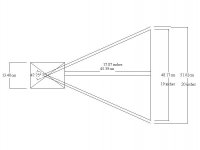
If you take a 48 degree angle and move it out from a flat surface about 15 to 19 inches and lengthen the angle lines out until they intersect the image plane. That is about the image size that the lens can focus.
If you don't have CAD software you can easily do this with a large piece of cardboard or paper, a protractor and a straight edge.
I will sketch a CAD drawing for you so you will know the total theoretical size that the lens can image. Be back in a few minutes.
Hezz
The FOV angle is usually quoted for the angle which is the angle between the axial center of the lens and the angle for which there has been correction made. This is because most lens systems are symetrical. Therefore the usable total angle is 48 degrees. Now the longer the FL is the farther the lens is away from the image source so the bigger image it can focus.
If you take a 48 degree angle and move it out from a flat surface about 15 to 19 inches and lengthen the angle lines out until they intersect the image plane. That is about the image size that the lens can focus.
If you don't have CAD software you can easily do this with a large piece of cardboard or paper, a protractor and a straight edge.
I will sketch a CAD drawing for you so you will know the total theoretical size that the lens can image. Be back in a few minutes.
Hezz
ROX,
If you can interpret this sketch one thing should become obvious.
This lens should in theory work with up to a 21 inch LCD. But you would probably need to project at least a 200 - 250 inch screen to get it to work. This is just estimate.
This is going to give some guys with a 600 watt metal halide bulb some
dangerous ideas. If your room was big enough and you made a monster projector you could use a 21 inch LCD and have a really large image.
Hezz
Attachments
well, i didn´t know that the field angle was the half angle so twice would be the correct one we can use to our setups.
i´ll check it with the manufacturer.
24 degrees (12+12?)
OR
48 degrees (24+24?)
sorry about confusing you.
i´ll check it with the manufacturer.
24 degrees (12+12?)
OR
48 degrees (24+24?)
sorry about confusing you.
Re: 24 degrees
Please could you tell us how?
Those are first hand specs;
450mm EFL ,
F=3,6
Clear aperture= 125mm
barrel lenght=150mm
midle element F stop aperture=109mm
Guy Grotke said:I calculated a full field angle of around 49 degrees for this lens, (using limited size data),
Please could you tell us how?
Those are first hand specs;
450mm EFL ,
F=3,6
Clear aperture= 125mm
barrel lenght=150mm
midle element F stop aperture=109mm
pretty simple really
The clear aperature and the middle element aperature would be important if we were using this triplet for photography. But we are not!
The fresnels are used to create a cone of light that could be focussed at the same plane as the optical center of the lens. The edges of that cone form a virtual aperature, since there is no light outside the cone. Assuming you use a 24 mm arc, 220 and 550 mm fl fresnels, and the LCD to lens distance is 528 mm, then the focussed arc image would be 60 mm long.
Draw a full-scale picture of the LCD and lens cross-section with the LCD on the left side. Draw the 60 mm arc image as a vertical line through the center of the triplet. Then draw a line from the upper edge of the arc image to the upper edge of the lens barrel. Measure the angle of that line from the central axis. That is the half angle. You can also extend the line to the left until it crosses the plane of the LCD. If it passes above the vertical line that represents the LCD, then all of the light passing through corner pixels can get to the arc image in the lens, and thus out the other side to the screen.
Of course, this is just a simple estimate. It assumes that the optical center of the lens is at the physical center, which may not be true. It also assumes the triplet is symmetrical, so light that gets in along the arc image path will also clear the opposite barrel. But it should be pretty accurate, since the lens could focus a clear image of a pixel even if some of the light from that pixel was blocked.
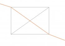
i would say that if we consider the refraction by the first and third lens the angle would be even smaller. forget by now the arc lengh and try to imagine a ligh ray from first lens upside passing throw midle lens elemnt and get outs from botton third elemnt. I think this is the critical ligh stop last ray. then if you consider the refranction by those two lenses (midle lens is not working) you would see the angle of the ray coming from lcd is smaller than the angle inside the triplet. Also we can say that the light would be dimer because of the arc lengh, but i don´t want to complicate more.
here is what i mean;
here is what i mean;
Attachments
- Status
- Not open for further replies.
- Home
- General Interest
- Everything Else
- The Moving Image
- Optics
- 135mm long-throw lense kit from diylabs