Clearing out some files, I had shared this on SkunkieDesigns’ forum for 300b amp builders there and thought it might help someone here.
I had seen photos @stephe had of wiring these components, and I wanted something a little more compact so I played around with the components a bit until I had them arrayed as in these photos.
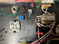
I spaced the mounting holes 50mm apart for closest workable distance between components.
White block is heat sink ceramic for better/more thermal conduction into an alloy heat sink..Drilled holes in scrap wood as a template and used Kynar shielded wire for output to filaments. Maybe not necessary, but I had it around and it can't hurt.
First, flip rectifier over to line up ++ and -- with Voltage Regulator, bend leads outward to align, put on some heat shrink for insulation, solder. Bend center AC leads UP and away from center. You can solder these easily once the units are mounted inside. leads are all about 3-5mm off the plane of the steel plate I used for the amp. top, no shorts/insulation required but it's good practice I think to put heat-shrink insulation on where I can "just in case."
Now attach tantalum 10uF cap. 22uF and output leads. Large filter cap leads are bent and cut about 5mm wider than the "rails"; insert one side under one rail and twist to get other side under previously soldered Ground - you might need to use a pair of needle-nosed pliers taking care to get capacitors/components in order: Rectifier out-6800uF Electrolytic cap-10uF Tant. Cap.- VR- 22uF Tant Cap - output. The 10uF cap in one pic close to the insulation was moved forward a bit for the 6800 uF cap. They work great.

I had seen photos @stephe had of wiring these components, and I wanted something a little more compact so I played around with the components a bit until I had them arrayed as in these photos.
I spaced the mounting holes 50mm apart for closest workable distance between components.
White block is heat sink ceramic for better/more thermal conduction into an alloy heat sink..Drilled holes in scrap wood as a template and used Kynar shielded wire for output to filaments. Maybe not necessary, but I had it around and it can't hurt.
First, flip rectifier over to line up ++ and -- with Voltage Regulator, bend leads outward to align, put on some heat shrink for insulation, solder. Bend center AC leads UP and away from center. You can solder these easily once the units are mounted inside. leads are all about 3-5mm off the plane of the steel plate I used for the amp. top, no shorts/insulation required but it's good practice I think to put heat-shrink insulation on where I can "just in case."
Now attach tantalum 10uF cap. 22uF and output leads. Large filter cap leads are bent and cut about 5mm wider than the "rails"; insert one side under one rail and twist to get other side under previously soldered Ground - you might need to use a pair of needle-nosed pliers taking care to get capacitors/components in order: Rectifier out-6800uF Electrolytic cap-10uF Tant. Cap.- VR- 22uF Tant Cap - output. The 10uF cap in one pic close to the insulation was moved forward a bit for the 6800 uF cap. They work great.