Hi all!
I need a power supply schematic (circuit) 12V to 250V/10mA for the magic eye with the em80 tube.
Preferably the schematic to be IC=NE555 or MC34063A.
thank you!
I need a power supply schematic (circuit) 12V to 250V/10mA for the magic eye with the em80 tube.
Preferably the schematic to be IC=NE555 or MC34063A.
thank you!
Last edited:
I've read about also a "diode string" but I recall it supplying not more of a couple milliAmpere 😛
That is not as easy as it sounds. The basic numbers are a 250 volt DC supply at 20 milliamps which is 5 watts.
If the convertor were 100% efficient then that implies a 12 volt device pulling over 400 milliamps. In practice so simple an arrangement would (assuming the 555 were driving a transformer in reverse) might be 30 or 40% at best. Its a non starter imo. Great in theory but in practice no.
I'm afraid I haven't any worked design examples for other possibilities either. Maybe the 'best' solution might be two small transformers back to back of 240 (110) to say 15 to 30 and a similar one in reverse fed from the first ones secondary.
OK,... well let be 250V/(6...10)mA.That is not as easy as it sounds. The basic numbers are a 250 volt DC supply at 20 milliamps which is 5 watts.
If the convertor were 100% efficient then that implies a 12 volt device pulling over 400 milliamps. In practice so simple an arrangement would (assuming the 555 were driving a transformer in reverse) might be 30 or 40% at best. Its a non starter imo. Great in theory but in practice no.
I'm afraid I haven't any worked design examples for other possibilities either. Maybe the 'best' solution might be two small transformers back to back of 240 (110) to say 15 to 30 and a similar one in reverse fed from the first ones secondary.
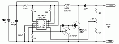
Is this schematic can?
Attachments
Last edited:
Do the maths 🙂 W=I*V so that's 250*0.01 which is 2.5 watts. That means you need to draw at least 0.2 amps at 12 volts (I=W/V) if it were 100% efficient. Such devices are not though.
Two small transformer just might get you what you want though. Expanding on what I mentioned earlier, the transformer voltages would need to be chosen either to give you enough overhead to use a simple regulator or calculated to give around 250volts DC under load.
Two small transformer just might get you what you want though. Expanding on what I mentioned earlier, the transformer voltages would need to be chosen either to give you enough overhead to use a simple regulator or calculated to give around 250volts DC under load.
This one is simple, gives you galvanically isolated HV on the secondary of the transfo. For 12V operation you will need a 9V to 230V transformer with the necessary power spec. Because it works at a few kHz range, you can use a smaller transfo (2.5-3 VA) On the 230V side use fast diodes , and HF electrolytics to get the 250V DC.
Attachments

Last edited:
- Status
- Not open for further replies.