So I recently bought a 12V SMPS that was supposed to be 120/240V but the factory made a change without telling the seller. Long story short I now have a 230V power supply in Canada.
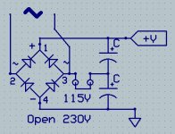
I've looked at the circuit and the 230V comes into a bridge.
If I change the bridge for a Delon voltage doubler it should work, no? Or supplying it with 300VDC instead of 230VAC as it will just go one way through the bridge?
Thanks in advance for your help.
I've looked at the circuit and the 230V comes into a bridge.
If I change the bridge for a Delon voltage doubler it should work, no? Or supplying it with 300VDC instead of 230VAC as it will just go one way through the bridge?
Thanks in advance for your help.
If you bought it from E-Bay request a return for item based on 'not as described'... Not sure about Distance Selling regulations in Canada but in the UK whenever that has happened to me I file for the return. The seller gets to pay the return costs and give a full refund. Many times they give a full refund and I get to toss the item in the recycling bin. Occasionally they try to 'do a deal' so I just quote distance selling regulations at them and then they fold. I am quite happy to eat my own mistakes but if someone sells me something that is not what they claimed it to be then they get to eat theirs.
I got a refund, I don't have to return it. That's why I want to mod it to be able to use it at 120V. And from looking at the circuit it appears to rectify 230V to make ~330VDC. Therefore it looks like I could run it from DC using a Delon circuit. Sine it was free I guess I could try it and see. Who cares if it blows up.
Did you try connecting it to 120V? Switching power supplies sometimes have very wide voltage range they work on.
^ That's what I would do. Many SMPS work down to 90 volts or even lower (sometimes a lot lower). Just fire it up and test it.
Does it use a high value resistor to aid start-up, or does it even use a resistor to power the primary control circuit ? The high value one could be in the 270k region and typically from unregulated rectified mains onto the switching transistor. If so then worth a tweak.
Obviously all just a generalisation and there are many different types out there.
Obviously all just a generalisation and there are many different types out there.
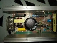
Could be. The resistor under that cap is 680k? There is a diode beside it that's blocked by the cap. Are you thinking it might be possible to lower that value to get it to fire on 120V?
EDIT: Never mind, that 680k resistor is a bleeder for the cap. The power comes through an NTC, into filtering (X2, Common mode choke) into the bridge. It looks like I can just run it from DC.
EDIT: Never mind, that 680k resistor is a bleeder for the cap. The power comes through an NTC, into filtering (X2, Common mode choke) into the bridge. It looks like I can just run it from DC.
Attachments
Last edited:
Don´t know what you exactly have but turning a full wave bridge into a doubler, "the way PC supplies do" may be as simple as cutting a track with an X Acto knife.
No need for an external doubler, you already have all you want/need.
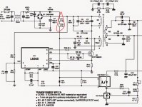
Just trace the voltage rectifier network (basically a bridge and 2 caps) and compare it to above posted schematic.
EDIT: thinking aloud: "unless you just have a single 400V cap" which some 220V only do.
But in that case adding 2 series caps to replace it is still no big deal.
No need for an external doubler, you already have all you want/need.
Just trace the voltage rectifier network (basically a bridge and 2 caps) and compare it to above posted schematic.
EDIT: thinking aloud: "unless you just have a single 400V cap" which some 220V only do.
But in that case adding 2 series caps to replace it is still no big deal.
Last edited:
Don´t know what you exactly have but turning a full wave bridge into a doubler, "the way PC supplies do" may be as simple as cutting a track with an X Acto knife.
No need for an external doubler, you already have all you want/need.
Just trace the voltage rectifier network (basically a bridge and 2 caps) and compare it to above posted schematic.
EDIT: thinking aloud: "unless you just have a single 400V cap" which some 220V only do.
But in that case adding 2 series caps to replace it is still no big deal.
Bingo! This supply has a single 450V 220uF cap. You've answered by question though. I'll still need to build the doubler circuitry externally because there's simply no room for two caps instead of one unless I might fit 2 470uF 250V caps inside.
Thanks.
Do you have off-board parts? If so then did you fuse the mains input, or are you just relying on on-board fuse?
If you increased the total capacitance, then you should check the NTC design (or you could get a fright when it fails).
If you increased the total capacitance, then you should check the NTC design (or you could get a fright when it fails).
Last edited:
No, I was able to fit the two caps neatly inside the casing after removing the original cap and drilling a third hole through an empty part of the board to connect the AC to the centre of the doubler caps. I'm using the original fuse, which, may or may not be rated at enough current for full power but it's working for my load (tube amp with boost converter for HV)
The capacitance is effectively the same. 220u vs 470u+470u in series = effective 235u. And as a bonus, the former "20A" (Sold as 240W, says 150W on the PCB artwork) power supply couldn't start into the load on the first try but this one can. It also runs like 10c cooler.
The capacitance is effectively the same. 220u vs 470u+470u in series = effective 235u. And as a bonus, the former "20A" (Sold as 240W, says 150W on the PCB artwork) power supply couldn't start into the load on the first try but this one can. It also runs like 10c cooler.
Last edited:
- Status
- Not open for further replies.
- Home
- Amplifiers
- Power Supplies
- 12V SMPS mod.