starting on the left.
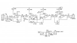
The two inputs through C/Ra and C2/R2 allow the first opamp to sum the input.
The VR when set to 47k gives an output that is L signal PLUS R signal.
When set to zero the output is zero.
The R3 sets the output offset. This should be equal to the parallel combination of E1||R2 ||VR .
It's MAXIMUM value should be ~ 15.7k.
You could set it a bit lower for less noise, if you measure the VR setting at your typical listening level and calculate the parallel combination. It could be anywhere from 1k to 12k.
The second opamp is some kind of filter that I don't understand. It is not S&K, nor MFB.
R6 seems far too high same reasons as previous.
I can't help any further.
The 3rd opamp looks like a unity gain buffer, but with both inputs connected to the same output I don't understand it. R11 is far too high. Same reason.
Th 4th opamp looks like 3rd: buffer, with both inputs connected to the previous output.R12 is far too high. same reason.
Output DC blocker is OK.
I/2 rail voltage divider is OK.
")
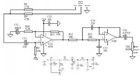
thank u andrewlebon sir. but we r using is preamp before 12v single supply power amplifier. actually this amplifier had a passive tone control previously but we are trying to make it as a mini sub-woofer with 12v linear supply. please give any nessessary changes to my schematics. thank u once again.
For trail we build the attached sch on a prototype PCB. Every thing connected but no sound coming from woofer, but the power amplifier ic is heating up. when we removed the preamp and connected signal directly the amp works nicely. please somebody give some advise or find some faults if any from the circuit.
Attachments
is this your design? or is it a copy of someone else's design?............... please give any nessessary changes to my schematics. ..........
Are the 2nd, 3rd and 4th opamps supposed to be S&K filters?
is this your design? or is it a copy of someone else's design?
Are the 2nd, 3rd and 4th opamps supposed to be S&K filters?
This schematic (first one) was drawn by seeing noname company subwoofer pcb. It was a gifted to one of my friends from their relatives.
post6 uses dual polarity opamps layout but with a single polarity supply. That won't work.
Either adopt dual polarity supply and dual polarity opamp layout
or
adopt single polarity supply and single polarity opamp layout with the 1/2Vcc taken to the input of every opamp.
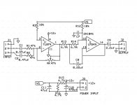
this sch was copied from 320v.com site. it was actually used with tda7375 ic subwoofer system. but my prototype didn't worked.
Cheap car subwoofer filter circuit | Amplifier Circuit
TL072 Car Subwoofer Filter Circuit ~Circuit diagram
Both circuits single 12 volt dc supply
TL072 Car Subwoofer Filter Circuit ~Circuit diagram
Both circuits single 12 volt dc supply
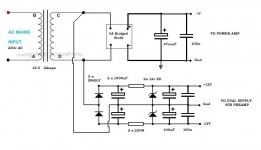
Andrew sir, i am using 12-0 2A transformer for my power amplifier. Can i connect another rectifier to the transformer as in the circuit below. Does the circuit works if i connect a dual supply preamp to the second rectifier? can both grounds be connected?
Attachments
Post 6 requires a dual polarity supply.
You have connected it to a single polarity supply.
It won't work.
Have you done something similar to the first sch in failing to correctly convert from dual polarity to single polarity?
Andrew sir, the post 6 which you told won't work was working perfectly. the culprit is a pot. i replaced the pot and the circuit worked.
Thanks for your advises.
That PSU is a disaster in waiting. Use another small transformer for the dual supplies.
Gajanan Phadte
there is no place in the box. otherwise i could had used the dual supply filters and rectifier plus a small transformer. place is the main thing. any way the circuit in post 6 worked perfectly.
- Status
- This old topic is closed. If you want to reopen this topic, contact a moderator using the "Report Post" button.
- Home
- Amplifiers
- Chip Amps
- 12v single supply subwoofer preamp