Proportional ground question
Hi forum techies'
Very recently I needed to install two spdt switches (w/LED on-off indicators) in my truck to be able to isolate/identify the 'left and right' side subwoofer amplifiers. There have been instances where the line signal from the hu was very weak or intermittent, due to a bad connection in the modular filter chain. Since the remote "trigger" was jumped between both subwoofer amps, there was no convenient way to do a proper "A-B" comparison, hence... this implementation. The information that I need now has nothing to do with the trigger circuit or the amplifiers, but the LED ON indicator. See, I installed these switches yesterday, during the day but had never driven the truck at night... 'til now.
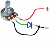
These leds are sooo bright that I had to cover them up just so I could see the road in front of me; the glare was absolutely blinding (maybe I'll get those uv blocking goggles "as seen on TV" for night driving!). I know I can put in a rheostat or a 'fixed resistor' to dim the light some, I just don't know what type of rheostat to get e.g., 12vdc, 2A max, range of ohms 250-500 etc... Can anyone tell me what type of rheostat specs to look for? PS: My plan is to use this rheostat on the "ground side" of the lighting circuit for convenience; just don't want to have to cut-up the new harness to separate the red (+) lighting wire from the N/O terminal at the switch base, here's a look at the switch:


Thanks, Greg (rigtec) cheers
Hi forum techies'
Very recently I needed to install two spdt switches (w/LED on-off indicators) in my truck to be able to isolate/identify the 'left and right' side subwoofer amplifiers. There have been instances where the line signal from the hu was very weak or intermittent, due to a bad connection in the modular filter chain. Since the remote "trigger" was jumped between both subwoofer amps, there was no convenient way to do a proper "A-B" comparison, hence... this implementation. The information that I need now has nothing to do with the trigger circuit or the amplifiers, but the LED ON indicator. See, I installed these switches yesterday, during the day but had never driven the truck at night... 'til now.
These leds are sooo bright that I had to cover them up just so I could see the road in front of me; the glare was absolutely blinding (maybe I'll get those uv blocking goggles "as seen on TV" for night driving!). I know I can put in a rheostat or a 'fixed resistor' to dim the light some, I just don't know what type of rheostat to get e.g., 12vdc, 2A max, range of ohms 250-500 etc... Can anyone tell me what type of rheostat specs to look for? PS: My plan is to use this rheostat on the "ground side" of the lighting circuit for convenience; just don't want to have to cut-up the new harness to separate the red (+) lighting wire from the N/O terminal at the switch base, here's a look at the switch:
Thanks, Greg (rigtec) cheers
Last edited:
To dim an LED you just need to add a resistor in series with it. Some modern LED's are super bright even on a milliamp or less of current. So for 12 volts supply try adding say a 10k for starters and then go higher or lower to suit.
To dim an LED you just need to add a resistor in series with it. Some modern LED's are super bright even on a milliamp or less of current. So for 12 volts supply try adding say a 10k for starters and then go higher or lower to suit.
Thanks Mooly,
One of the reasons that I wanted to use a rheostat is so I could regulate the light some; and no hit or miss. Any idea about the resistance value range on a dimmer? Thanks for your reply!

Try inserting a 1k 1/2watt resistor in series with the LED's. If too dark use 470R if still too bright try 2k2.
Try inserting a 1k 1/2watt resistor in series with the LED's. If too dark use 470R if still too bright try 2k2.
Hi Jon'
Okay, I'll try a 1k ohm 1/2w (fixed) resistor, then 470 ohm 1/2w...etc! Thanks Jon, for your reply and help; I'll post back later to report results.
rig, regards!
Or... you could add something like a 100K pot in series with the LED's. If you have more than one LED (two switches ?) then this method allows the LED's to be series connected.
Hi Mooly,
Thank you so much for your replies and help; very sincerely! I've been thinking about everything you've posted and I'd like to respond. These switches are the third set that I've implemented since I got the idea. The first set was red but were supposed to be "Burnt Orange" to match the instrument cluster. The next set included one that was defective; internally cross circuited which caused the LED to stay on all the time. So I replaced those w/these.
Now, because I fabricated the harness in such a way that integrates the LED (+) with the N/O terminal, I'd prefer not try and separate these from the pins because it's so difficult to keep the switches internal circuitry cool while making the solder connections, and it takes about 6 weeks to have them shipped from "Honk Kong". But here's what I hope to do. The LED terminals are (-) and (+) and I already have the (+) soldered to the normally open terminal. But... the (-) neg wire is going straight to a ground in the console.
So I think I can direct the neg led wire through the 100K ohm rheostat, then to ground; so the light is energized first (upstream), and then connects to the rheostat, see below:
The black part of the sketch was pre-existing. The blue ink was added on today, after you posted your rheo. All I'm really doing is feeding the (+) LED from the n/o terminal of the sw. After current passes through the light, it hits the rheo (Red + wire) goes through the resistor, and leaves through the middle (center) wire to ground. I think it will still work, any thoughts...
PS: Thanks Mooly, for moving all these threads around! I just saw what you did about a min ago; I was busy drafting this post... glad you didn't delete this before I was done 😀
cheers!
I think I follow you 😉 The switch, the LED and the resistor are just a series circuit and so it doesn't matter what order things are connected.
"This must be the messiest thread EVER!" Nah, there's worse 😀
(Trouble with merging threads and posts is that the timeline is unalterable and fixed by the forum software... but, if you want any posts deleting then just list them and they can be zapped 🙂)
That's me done for tonight anyhow...
"This must be the messiest thread EVER!" Nah, there's worse 😀
(Trouble with merging threads and posts is that the timeline is unalterable and fixed by the forum software... but, if you want any posts deleting then just list them and they can be zapped 🙂)
That's me done for tonight anyhow...
That's it Mooly,
It's all in series, hope it works. I'll be sure to report back after I hit Radioshack!
best to you! Greg, (rigtec)
It's all in series, hope it works. I'll be sure to report back after I hit Radioshack!
best to you! Greg, (rigtec)
Okay gents, I'm here to report that... "HOUSTON, WE HAVE A PROBLEM!" Hahahaha!
There is a new situation that's come about since we chatted on Fri; a phenomenon not quite understood that I've considered over the last several hours, and I'm still finding it difficult to explain right now; I'll tell you about that in just a moment but first, here's what happened after our last exchange. I went to Radioshack about three blocks up the street. I rummaged through the resistor bins and latched onto a couple of small, 10K potentiometers and decided to get them both.

I chose the one on the left to use, the one on the right seemed like it would be right at home in a big screen tv or something. I wanted to run a dry test under the hood using the rheostat and LED, but it started to pour out there and I didn't plan to go out in that, but...

TA-DAAAA! Just two 6v lantern batteries wired together in series! This "volume control" also has N/O & N/C contacts, so I wired them into the resistance circuit as well. I also measured the resistance potential and it offered a very smooth curve.


After the soldering work was done, I prepared the lil' resistor for installation:


Wrapped in a foam cloak, it was now ready to be put into service. It tested very well, from the brightest to the darkest (kinda hard to tell from these pics), I was more than satisfied:
Brightest

Darkest

Everything seemed to be just fine, "with both amps turned on". What I didn't realize yet was, when imposing resistance on the ground circuit, if only one switch is on (while dim), both icons will light up! Doesn't matter which one. I need to say that again. If both switches are on (pushed in), there's no problem. But if I'm dimming the status indicators a bit w/only one switch on, you'll watch the other switch suddenly light up. This doesn't happen when I have the potentiometer dialed to zero ohms (brightest).
Now I'm sure it's "feeding back" (somehow) through the other circuit, likely due to the fact that it's looking for a ground, I'm just not sure how it's cross circuiting. I've considered trying to use the rheostat on the hot side (that probably would solve the whole problem), but remember that this circuit is really there for one thing, to start/run the amps; you can't do that with 8 or 9 volts. So the hot wire (trigger) which feeds the sw common terminal needs to be @12vdc all the time: the ground circuit is only there for the light.
Well anyway, for now I've left the dimmer circuit in tact because these switches do still do their job, which is to allow me to check the amps individually when I need to. And the dimmer allows me to see where I'm going at night w/o that blazing 'Kriptonite' electric green blinding me wherever I go. Has anyone ever had this happen before?
Greg, (rig) regards
There is a new situation that's come about since we chatted on Fri; a phenomenon not quite understood that I've considered over the last several hours, and I'm still finding it difficult to explain right now; I'll tell you about that in just a moment but first, here's what happened after our last exchange. I went to Radioshack about three blocks up the street. I rummaged through the resistor bins and latched onto a couple of small, 10K potentiometers and decided to get them both.
I chose the one on the left to use, the one on the right seemed like it would be right at home in a big screen tv or something. I wanted to run a dry test under the hood using the rheostat and LED, but it started to pour out there and I didn't plan to go out in that, but...
TA-DAAAA! Just two 6v lantern batteries wired together in series! This "volume control" also has N/O & N/C contacts, so I wired them into the resistance circuit as well. I also measured the resistance potential and it offered a very smooth curve.
After the soldering work was done, I prepared the lil' resistor for installation:
Wrapped in a foam cloak, it was now ready to be put into service. It tested very well, from the brightest to the darkest (kinda hard to tell from these pics), I was more than satisfied:
Brightest
Darkest
Everything seemed to be just fine, "with both amps turned on". What I didn't realize yet was, when imposing resistance on the ground circuit, if only one switch is on (while dim), both icons will light up! Doesn't matter which one. I need to say that again. If both switches are on (pushed in), there's no problem. But if I'm dimming the status indicators a bit w/only one switch on, you'll watch the other switch suddenly light up. This doesn't happen when I have the potentiometer dialed to zero ohms (brightest).
Now I'm sure it's "feeding back" (somehow) through the other circuit, likely due to the fact that it's looking for a ground, I'm just not sure how it's cross circuiting. I've considered trying to use the rheostat on the hot side (that probably would solve the whole problem), but remember that this circuit is really there for one thing, to start/run the amps; you can't do that with 8 or 9 volts. So the hot wire (trigger) which feeds the sw common terminal needs to be @12vdc all the time: the ground circuit is only there for the light.
Well anyway, for now I've left the dimmer circuit in tact because these switches do still do their job, which is to allow me to check the amps individually when I need to. And the dimmer allows me to see where I'm going at night w/o that blazing 'Kriptonite' electric green blinding me wherever I go. Has anyone ever had this happen before?
Greg, (rig) regards
OK, a bit hard to visualise all this from descriptions but here goes with a couple of suggestions...
One option would be to use a dual gang (stereo) pot and wire each LED separately to one gang.
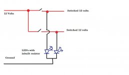
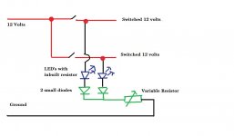
Another option, and this is where I have to guess how it really is, is to connect as shown here and add a couple of diodes to prevent the LED seeing a reverse bias. If the switch (or raher the LED) is suitable for AC operation as standard then this diode would already be incorporated in the switch.
So guessing how it all looks, here is the original switch with nothing added and then a possible workaround. The stereo gang pot would be a definite option because the two LED's couold never interact.
One option would be to use a dual gang (stereo) pot and wire each LED separately to one gang.
Another option, and this is where I have to guess how it really is, is to connect as shown here and add a couple of diodes to prevent the LED seeing a reverse bias. If the switch (or raher the LED) is suitable for AC operation as standard then this diode would already be incorporated in the switch.
So guessing how it all looks, here is the original switch with nothing added and then a possible workaround. The stereo gang pot would be a definite option because the two LED's couold never interact.
Attachments
OK, a bit hard to visualise all this from descriptions but here goes with a couple of suggestions...
Hi Mooly,
What you've described is 100% accurate, dead on! It was difficult to describe what I saw going on last night; would've needed to shoot a video to illustrate this behavior properly.
One option would be to use a dual gang (stereo) pot and wire each LED separately to one gang.
Wiring a dual gang pot is not a problem, but do you mean implementing this on the hot side or the gnd side?
Another option, and this is where I have to guess how it really is, is to connect as shown here and add a couple of diodes to prevent the LED seeing a reverse bias. If the switch (or raher the LED) is suitable for AC operation as standard then this diode would already be incorporated in the switch.
After you mentioned AC voltage, my heart quit the job for a bit, so I rechecked the product description (very scary!)... All is well though! The switch is rated for 250vac, the LED however is not, as it is to be used in a car application:
16mm 12V Car Black Aluminum LED Power Push Button Metal Switch Latching
(by Meco) Color: Green
* Easy to install, screw clamp type terminals to make fitting very easy.
* LED built on it's own circuit , lighted when on. or could be wired to make it
lighted alternate.
Details:
* Latching type, push it-- on, Push it again--Off
* Switch Rating: 3A/250VAC
* LED voltage: 12V only
* Contact Configuration: 1NO1NC
* Flat Head BUTTON
* Button Diameter : 10mm
* Head Diameter : 18mm
* Hole size required : 16mm
* Depth inc contacts : 36mm
"...So guessing how it all looks, here is the original switch with nothing added and then a possible workaround. The stereo gang pot would be a definite option because the two LED's couold never interact."
I'm still with you on that, however I did 'unintentionally' leave out one important detail. When I disconnected/broke the ground circuit (through the pot's N/O contacts), the led still demonstrated this same strange behavior; that same dim glow on both leds no matter what you do. So I'm not sure if adding diodes to the gnd circuit can address this issue; I may need to approach this from the hot side 😕
If I were to use a fixed resistor across the "N/O and (+) LED" terminals at the switch base, could I use a low value resistor (1K-4K)? 1. there's not a lot of room to play with there, and 2. There is a good chance of burning the switch's entrails by reheating them, so I was definitely hoping to avoid doing that... if I burn them, it'll be a good month before "Hong Kong" can ship me more (only cost about $9 bucks though): Amazon.com - 16mm 12V Car Black Aluminum LED Power Push Button Metal Switch Latching - Electronic Component Pushbutton Switches
Thank you so much for all your help, this is a great learning/training experience for me!
rig
Again, its very very difficult to visualise all this. Do you need the option of "dimming to zero" ? or using the switch to cut the LED's off completely ?
Back to the second drawing I did...
That should work. If both switches are on then both LED's see 12 volts applied. The lower end goes via a diode and into the common pot. That should work and dim both OK. If you turn one switch off then the 12 volts to that particular LED is removed. This is where the diode comes into play. With no 12 volts on the LED anode (top lead) and with a variable (depending on pot setting) voltage on the lower end of the diode, then the diode is non conducting and no LED current flows. So that one LED is off while the other is still on and dim-able.
One possible problem (something for you to check) is to make sure that the switched voltage really does fall to zero when off and that there is no back feed from somewhere else via the amp and back onto that line. Even 3 or 4 volts would make the LED glow. So that is worth checking.
To be honest, I never did check the N/O switch term when 12v operative, but did however, test the new switches on the bench using an ohm meter across com and n/o terms and it showed no continuity or open between them. I just realized that I can implement a concentric pot on the hot side, between the n/o and pos light term without using the soldering iron. I can cut the light jumper here:

...crimp a male and female stake-on onto the two wires and connect a new dual pot between them. Again I'll report back after picking up what I need/installing. If this doesn't work, for whatever reason, I think I'll put the original "green ring" switches back in and mitigate my troubles. Thanks again for replying.
...crimp a male and female stake-on onto the two wires and connect a new dual pot between them. Again I'll report back after picking up what I need/installing. If this doesn't work, for whatever reason, I think I'll put the original "green ring" switches back in and mitigate my troubles.
Thanks again for replying.Your welcome 🙂
Remember it all makes sense to you because you can see it 😀, its very difficult following descriptions. The switches will read perfectly on the bench. Its when fitted that you need to confirm that there is no voltage creeping onto the supposedly off line via all the amps and electronics... again I say that as a safeguard and a check because I can't see if that would be possible or not with the set up you have.
If you get stuck though... ask 🙂
Most definitely will! I'm glad this is not a "serious problem" like involving no audio, OH MY! 😱 haha!
rigtec:
It appears that there are placeholders for photos but they're not showing up on my computer.
It appears that there are placeholders for photos but they're not showing up on my computer.
rigtec:
It appears that there are placeholders for photos but they're not showing up on my computer.
Hi Perry,
I'm not sure what the trouble is, I can see them using 'Chrome' and 'Dolphin' on android. I pasted them (
Hey Perry,
I just tried to view them using Firefox and I can't see them either. I'll try to figure out what's going on.
I can't believe this. I've got 20 or 30 pics on this thread as illustrations to document a problem, and didn't know until now that you weren't seeing them.
I just tried to view them using Firefox and I can't see them either. I'll try to figure out what's going on.
I can't believe this. I've got 20 or 30 pics on this thread as illustrations to document a problem, and didn't know until now that you weren't seeing them.
Last edited:
- Status
- Not open for further replies.
- Home
- General Interest
- Car Audio
- 12v Rheostat question