Dear All,
I'm building push pull converter for an audio amplifier.
I see many car audio amplifier's power supply is open loop push pull type, without an inductor on its output.
My question is:
1. Which is better? open loop or closed loop?
2. Since iron powder core are really hard to find in here. I was
thinking, to build this PSU without output inductor. Is there any
effect on audio performance or any other effect by leaving out
the output inductor?
3. The output voltage is +75 -0- -75, if I use the output inductor,
I'll need 2 inductor. Should it be coupled into one single core?
Thanks
1. Which is better? open loop or closed loop?
Open is easier for you.
2. Since iron powder core are really hard to find in here. I was
thinking, to build this PSU without output inductor. Is there any
effect on audio performance or any other effect by leaving out
the output inductor?
You might be able to get by without the inductor if your duty cycles are kept to the maximums.
3. The output voltage is +75 -0- -75, if I use the output inductor,
I'll need 2 inductor. Should it be coupled into one single core?
I think it is good to consider the latter approach if you decide to regulate the outputs.
Electron,
Yes, I know open loop will be much easier. But considering audio performance. I think it might be better to go with closed loop.
But, there is another problem now.
In car audio, people usually separate the input ground and output, because of noise.
That's will be complicated in feedback circuit, since the ground are not at the same potential.
1. Do you have any information, how to do the feedback with
optocoupler?
By the way, I can't find any iron powder here. So I'll use ETD39 ferrite core, wound in opposite direction for each output. It comes from TV, seems to be N87 material. And there is a large air gap, around 1.5mm. So the AlnH could be around 150, quite close to iron powder.
As I understand the lower AlnH, the higher allowable operating frequency will be.
2. Do you think this will work?
In attachment, is calculated closed loop bode plot of this PSU(type 3 compensation). if ground are not separated. There is a peaking. Is that good?
Attachments
I am quite specialized in my theoretical knowledge, but I will offer what thoughts come to me.
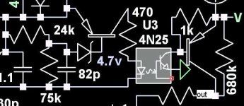
I use a PNP transistor on the diode side of the optocoupler instead of a TL431. The output from collector of the second transistor could connect to the controller IC you choose, but I use my own more discrete control method and am not sure how well it would work on a standard controller IC.
Iron powder has a lossy aspect which you may find difficult to reproduce with ferrite. You may be able to help the situation with damping circuits across the windings if you end up with a problem.
I suspect that, according to that bode plot, your loop will be unstable. It is just my impression and am not sure.
In the diagram, the output voltage is determined by the ratio of the 24k/75k resistors. You would need to change the ratio. The 470 current limiting resistor needs to be increased to at least a few k since this circuit is for 12v. The emitter of the second transistor goes to the reference power supply. The 680k sets the maximum duty cycle. Its value depends on the PWM frequency.
Attachments
Powered iron is much lossier than ferrite and I agree your bode looks like it will be unstable. You really need an inductor since the output caps will see the reflected switch current. Unless of course you are running full pulse width.
Can you post a schematic?
Can you post a schematic?
- Status
- Not open for further replies.