So you think the idea using 2 to-220 style amp chips with inverted phase driving each side of the coil will work well as in post #2? I personally can't think why it wouldn't work as speakers are coils, just maybe with lower inductance.
If so I will order the parts and try it out.
If so I will order the parts and try it out.
The problem I had with similar idea is that whatever happens on the transformer output is reflected back into the primaries, destroying the devices. Feeding it with a pure sine wave does not mean that everything is good, the current could be lagging, all kinds of things that you do not expect. Once it takes a load other than resistive your feedback circuits need to compensate. The thing I was playing with was a bridged 1.6KW amp driving driving a 12V transformer, as soon as I loaded it with inductance the thing simple popped 24 output transistors per amp. These chips are necessary to make something reliable and fool proof. Best results was obtained with Class D run at HF and small transformer but there are still many considerations. Try your idea by using car amps. These ferrite transformers only have a few windings and easy to make up yourself. Power transformers as we know them is just plain trouble.
Last edited:
You must misunderstand what I am asking. I don't know where you got the notion that I am powering the heaters with AC. It is a 12VDC adapter.
I want to make a inverter powered by a 12V wall-wart adapter to power valve heaters with the low side
Unless I don't understand English (I am not a native speaker) it says that you make an inverter to power valve heaters with the 12V AC. From the low side of the transformer.
I said digital and solid state. And a 12V Wall-Mart power supply does not sound like something sufficient to power a class A final stage. So I assumed you wanted a tube pre-amp.And whats digital about vinyl and a class A output?
Yes, it could work, but you need to add 4 diodes between the outputs and the supply rails to protect the chips against inductive kickbacks, and you have to derate the output power to take into account losses and the non-unity cos phi of the load: for example, if you use two 20W capable chip amps, the final usable will be ~20W, not 40WSo you think the idea using 2 to-220 style amp chips with inverted phase driving each side of the coil will work well as in post #2? I personally can't think why it wouldn't work as speakers are coils, just maybe with lower inductance.
If so I will order the parts and try it out.
I found something similar at ESP Projects:


The differences being that my idea proposes 2 amps driving each side of the transformer in bridge mode thus no AC coupling cap would be needed. (C3/C2 in the above schematics).
I only hope ~20W amp chips have enough power to drive the transformer (should only be about 1.6A RMS).
I have used the transformer in a back-to-back configuration before for measurements here: https://www.diyaudio.com/community/...-reverse-safety-and-performance.409204/page-3
Link to sound-au project: https://sound-au.com/project238.htm

Yes, but the idea is the closest I can find, that is driving a transformer with a power opamp. I will be using a sine (thus no harsh transients), but the above design's a square.
One concern I do have is any DC voltage offset between the 2 amp's may result in early saturation of the coil if not kept to a minimum? And I want to avoid the coupling cap if I can.
One concern I do have is any DC voltage offset between the 2 amp's may result in early saturation of the coil if not kept to a minimum? And I want to avoid the coupling cap if I can.
Last edited:
Perhaps use DC for the heaters, and an off-the-shelf boost SMPS from 12V for the HV supply? Probably need some care to filter out switching noise, but its a simpler solution.
If going the pure sine wave route a DDS generator (such as AD9833 module) could be the initial signal source, and enables experiments with both low frequency and mains transformer, or high frequency (ultrasonic) step up ferrite transformers.
If going the pure sine wave route a DDS generator (such as AD9833 module) could be the initial signal source, and enables experiments with both low frequency and mains transformer, or high frequency (ultrasonic) step up ferrite transformers.
There's an open-access X-chapters section on this on the Art of Electronics website.
I think they used a square wave, which was then passed through a resonant RLC filter to get a sine wave output.
I think they used a square wave, which was then passed through a resonant RLC filter to get a sine wave output.
I think I found it.There's an open-access X-chapters section on this on the Art of Electronics website.
Link: https://x.artofelectronics.net/wp-content/uploads/2019/11/9xp14_low-noise_isolated-pwr.pdf
Seems it could be a good method if it will work well at low frequency's, but would still need something like a classic 555 to drive it?
But in terms of simplicity and 'just works' the ICL8038 looks hard to beat, here's a buffered sine from the datasheet:
Link: https://www.mit.edu/~6.331/icl8038data.pdf
AC for heaters was a low cost solution
DC being more ideal.
Being B1 voltage and B2 voltage
Stands for =Battery
And 6 and 12 volt heaters specifically designed
for common 6 volt or 12 volt cells
So I don't even understand the purpose.
Being the power source is already DC
Otherwise re inventing the wheel isn't necessary
Being that efficient pure sinewave convertors
have already been designed.
And Texas Instruments and many others already
have design applications published for specific
driver IC's
@WhiteDragon - Can you name the model of any such IC's?
All I can find are chips like SG3525 and CD4047 but those are square drivers.
All I can find are chips like SG3525 and CD4047 but those are square drivers.
Isolation? Some tubes appear to have heaters hard-wired to the cathode, so an isolated transformer tap could allow 2 tubes to be stacked?So I don't even understand the purpose.
Being the power source is already DC
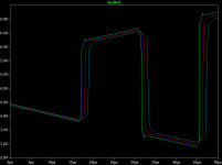
Will mention again, you don't need a sine wave to get a low noise DC output. (I cited some of the white papers done by the late Jim Williams on low noise high voltage circuits for Linear Tech, now part of Analog Devices). Chips like the LT3439 modify the transition time so that the edges, the rate of change rounds the top and bottom of the pulse so di/dt is slowed. The picture below shows how stepping the value of the slew control resistor (on the example from LTSpice). As the resistor value increases, di/dt is slowed.
The advantage of slew control over sine wave is much greater efficiency.
The advantage of slew control over sine wave is much greater efficiency.
Attachments
Hello,
This may interest you.
I have this DC-AC module project that is in the final stages of development. It will allows to heat in AC all kinds of tubes including 300B.
I started to assemble information on this project on my Github repository.
Don't ask me if I've ever tried the DC-AC module on a real tube amp. 😳 Not yet.
I'll have to find some testers, by the way.
Regards,
Stef.
- Home
- Amplifiers
- Power Supplies
- 12V pure sine wave Inverter using op-amps.