WoW
0.o
Now this is just beautiful, you probably can't add the schema if you have it, can you?
This would be perfect for small scale one. If it is not that difficult, could you add a picture of bottom side.
Great, great job done here.
0.o
Now this is just beautiful, you probably can't add the schema if you have it, can you?
This would be perfect for small scale one. If it is not that difficult, could you add a picture of bottom side.
Great, great job done here.
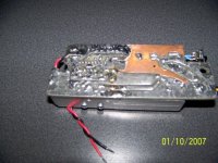
Thanks Luka. Yes, I will get to the schemo tonight, and a pic of the underside, too. The board's dimensions allow it to fit inside the enclosure of a gutted Dell laptop power supply. Showed it off at my ham radio club's monthly meeting last night. 2 guys wanted one each. 😀 😀
The Good, the Bad, and the Outright UGLY!
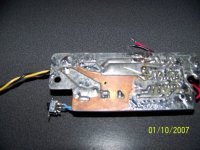
I must warn you, though, that it is not pretty. My lame-a$$ version of wave soldering has left some copper exposed on the underside, which has begun to oxidize. I could pretty it up with a little Scotch Brite scrub pads................
I must warn you, though, that it is not pretty.
My lame-a$$ version of wave soldering has left some copper exposed on the underside, which has begun to oxidize. I could pretty it up with a little Scotch Brite scrub pads................Well,
Since you ask, it will work all the way down to 8V (the SG3525's UVLO is from 6-8V), and up to, say, 16V? Its output is switch-selectable at either 16- or 20V. This was originally for a friend, but when I powered it up, I promptly blew a 10A Slow-blow fuse. I panicked and built him a 2-chip SimpleSwitcher, instead, and kept this one for myself. After a couple of months looking at it on the shelf, I rolled up my sleeves and set about troubleshooting it. Turned out there was a solder bridge from one of the 3525's outputs to ground, killing the 3525. Fixed it and popped in another 3525 and tested it. Waveforms looked good, and got progressively fatter as I increased the load. At 20V out, I loaded it with a 4W 10W power resistor combo, only for a few seconds. At the 20V setting, it dropped only 30mV from no-load to full-load. MOSFETs, diode and PWM chip all stayed cool, but core heated a bit then stabilized out at ~30 degrees Centigrade.
I have tested it up to 5A, but I believe it could go higher because the MOSFETs are 75N06s, and the MBR2545CT Diode is rated for 25A (12.5A per leg). Here are a few pics of the underside.
Attachments

Hi Steve
Looks bad?That is not bad at all... I have seen worse that came from myself😀, but at the end it did still work🙄
Where is schema? I've must missed it somewhere...
Looks bad?That is not bad at all... I have seen worse that came from myself😀, but at the end it did still work🙄
Where is schema? I've must missed it somewhere...
Fell asleep 😴 at the keyboard as I was uploading the last pic. Needless to say, I didn't finish the schemo yet. 4-day weekend coming up, not too many projects, so I will git-er-done today or tomorrow, and then upload it.
Oh, if I only had a wave solder machine (and a pc board-making company..
Oh, if I only had a wave solder machine (and a pc board-making company..
I'm also contemplating something like this to power my laptop from the car lighter plug.
I need something at 12Vin and 16V @4.5A out. would a boost converter be fine or the current draw be too much for that topology? low ESR caps are nowhere to be found here.....
I'm thinking of making two units, a boost converter for a friend (same laptop requirements) and mine would use a half bridge (similar to a car amp's but only one output)
what would be a better/easier way to go?
I would say better would be "half bridge" more like push-pull, but only if you intended to have single phase boost converter.If more phases then if will be better to go with boost.And boost is easyer to go with.
sorry, I forget the correct term for it. I meant push-pull. 😀
multiphase would easily get complicated so push-pull might be the way to go.....
what about doing a boost converter but use both complementary outputs of the PWM oscillator so one inductor is storing energy while the other is powering the load. might not be a new trick but it just popped in my head. 😉
Well now,
I don't need to post a schemo. 😎 DJ nailed it! That is EXACTLY the circuit I did. A 2-Phase Boost converter. See post #8😎
Seriously though, I will finish it in my CAD program and post it ASAP.
I don't need to post a schemo. 😎 DJ nailed it!
That is EXACTLY the circuit I did. A 2-Phase Boost converter. See post #8😎 Seriously though, I will finish it in my CAD program and post it ASAP.
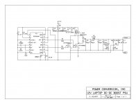
12V to 20V 2-Phase DC-DC Boost
Luka, et.al,
Here is the schematic, FINALLY!..... 😎 😀
😎 😀
As you can see, the SG3525 drives the two MOSFETS in a 2-F topology, at 50kHz each (100kHz clock).
Inductor L1 is 24T of #18AWG wound bi-filar on a T-80-26 powdered-iron toroid colored yellow-white. L2 was lifted from an old ATX psu, and was the output inductor for the +12V section. Since the max voltage either MOSFET will ever have to stand off is 40V (2 x the 20V boost on the 2-winding coil), I thought 60V units would suffice. Switch S1 switches the output between 16v & 20V, beacuse the converter originally was for two different laptops. As this need change, and then went away all together, I decided to still leave it in, in case my needs ever changed (again!).
Last night, I loaded it down to about 6A using 3- 10W 10W resistors paralleled. IC1 stayed cool, the Q1 &Q2 barely got warm (probably because their Rds(on) is only 9mW); L1 heated up then stabilized out just like before; D2 was moderately warm, though not as warm as L1, and L2's temp did not change perceptably.
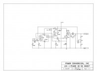
Next, I will post my single-F boost, controlled by a UC3843BN current-mode PWM chip. I have not yet built this one, and it may take a back seat as other, more important projects take precedence.
Ask me any question you may have, PLEASE! 😀
Luka, et.al,
Here is the schematic, FINALLY!.....
😎 😀As you can see, the SG3525 drives the two MOSFETS in a 2-F topology, at 50kHz each (100kHz clock).
Inductor L1 is 24T of #18AWG wound bi-filar on a T-80-26 powdered-iron toroid colored yellow-white. L2 was lifted from an old ATX psu, and was the output inductor for the +12V section. Since the max voltage either MOSFET will ever have to stand off is 40V (2 x the 20V boost on the 2-winding coil), I thought 60V units would suffice. Switch S1 switches the output between 16v & 20V, beacuse the converter originally was for two different laptops. As this need change, and then went away all together, I decided to still leave it in, in case my needs ever changed (again!).
Last night, I loaded it down to about 6A using 3- 10W 10W resistors paralleled. IC1 stayed cool, the Q1 &Q2 barely got warm (probably because their Rds(on) is only 9mW); L1 heated up then stabilized out just like before; D2 was moderately warm, though not as warm as L1, and L2's temp did not change perceptably.
Next, I will post my single-F boost, controlled by a UC3843BN current-mode PWM chip. I have not yet built this one, and it may take a back seat as other, more important projects take precedence.
Ask me any question you may have, PLEASE! 😀
Attachments
Hi Steve
Coil is winded like in half bridge, and connected too?
Current must add(in core), right?
Coil is winded like in half bridge, and connected too?
Current must add(in core), right?
hey steve,
answers to your questions,
1- it is push - pull
2- isolated
3- sure, you can use at car for powering alaptop
4- you must make this transformer your selves
5- you can use a core from one of the PC PS Ei series
is it ok?
answers to your questions,
1- it is push - pull
2- isolated
3- sure, you can use at car for powering alaptop
4- you must make this transformer your selves
5- you can use a core from one of the PC PS Ei series
is it ok?
hmmm.SG3525 is available here but costs around 2.5X a TL494. I'll try to adapt the circuit to use TL494. 😀
Luka,
Actually, it is wound like the primary of a center-tap push-pull, but with no secondary. Instead, the boosted voltage is tapped at the sources of the MOSFETs, and fed to the common-anode diode. So the center-tap goes to +12V and each end is connected to its respective source MOSFET pin. Since both windings never conduct at the same time, additivity or subtractivity really doesn't matter. Think of it as 2 separate boost converters, but with their inductors wound on the same core because each converter's waveform is synchronized 180 degrees out-of-phase with the other. Clear now? 😕
😕  😀
😀
Adnancoskun,
Answers:
1) Yes and No. Yes, it is wound like a push-pull, but, No, it does not operate like a push-pull forward. It is an "interleaved" flyback (Energy is stored, then released, not transferred as in a forward converter). I guess you could call it a "push-pull flyback". :bs:
2) No, this topology is not isolated. If isolation is necessary, just wind a complete transformer with primary(ies) and secondary(ies), but use ferrite, NOT powdered iron.
3) Yes, powering a laptop was the intention all along. I just wanted to be the first kid on my block to say "I have a 2-F interleaved flyback laptop power supply"! 😀 😀
4)Yes, you must wind it, but that's OK. This one only took me a few minutes.
5) I DID use a core from a pc supply. The T-80-26 core came from a rather weak-kneed AT supply (only 145W, but still a half-bridge & not a flyback), and not like the current ones that have a T-106-26 toroid core in them.
DJ,
If you do the TL494 (and this would work perfectly fine), I would do the NPN-PNP buffer like what it appeard gev did for his DC-DC boost converter.
Actually, it is wound like the primary of a center-tap push-pull, but with no secondary. Instead, the boosted voltage is tapped at the sources of the MOSFETs, and fed to the common-anode diode. So the center-tap goes to +12V and each end is connected to its respective source MOSFET pin. Since both windings never conduct at the same time, additivity or subtractivity really doesn't matter. Think of it as 2 separate boost converters, but with their inductors wound on the same core because each converter's waveform is synchronized 180 degrees out-of-phase with the other. Clear now?
😕 😀Adnancoskun,
Answers:
1) Yes and No. Yes, it is wound like a push-pull, but, No, it does not operate like a push-pull forward. It is an "interleaved" flyback (Energy is stored, then released, not transferred as in a forward converter). I guess you could call it a "push-pull flyback". :bs:
2) No, this topology is not isolated. If isolation is necessary, just wind a complete transformer with primary(ies) and secondary(ies), but use ferrite, NOT powdered iron.
3) Yes, powering a laptop was the intention all along. I just wanted to be the first kid on my block to say "I have a 2-F interleaved flyback laptop power supply"! 😀 😀
4)Yes, you must wind it, but that's OK. This one only took me a few minutes.
5) I DID use a core from a pc supply. The T-80-26 core came from a rather weak-kneed AT supply (only 145W, but still a half-bridge & not a flyback), and not like the current ones that have a T-106-26 toroid core in them.
DJ,
If you do the TL494 (and this would work perfectly fine), I would do the NPN-PNP buffer like what it appeard gev did for his DC-DC boost converter.
- Status
- Not open for further replies.
- Home
- Amplifiers
- Power Supplies
- 12v=19v 4,7A dcdc