12Ay7/6SN7 preamp PSU check
Hi all-
I was wondering if someone could give this PSU a look over to see if there is anything obviously wrong with it? It looks ok to me, but I'm still learning.
I saw this preamp from Joel on another thread, and it looked simple enought to make as I have most of the parts.
My difference is I'm using a PT from an old Hallicrafters S-40A (don't worry, it's my spare parts donor and in no way pristine).
The spec's on the transformer are 330-0-330 secondary @67mA, so it has a little more voltage than I need. This is the reason that I had to change the original power supply posted with this schematic.
Thanks in advance.
Glenn
Here's the PSU:
Here's the circuit:
Hi all-
I was wondering if someone could give this PSU a look over to see if there is anything obviously wrong with it? It looks ok to me, but I'm still learning.
I saw this preamp from Joel on another thread, and it looked simple enought to make as I have most of the parts.
My difference is I'm using a PT from an old Hallicrafters S-40A (don't worry, it's my spare parts donor and in no way pristine).
The spec's on the transformer are 330-0-330 secondary @67mA, so it has a little more voltage than I need. This is the reason that I had to change the original power supply posted with this schematic.
Thanks in advance.
Glenn
Here's the PSU:
An externally hosted image should be here but it was not working when we last tested it.
Here's the circuit:
An externally hosted image should be here but it was not working when we last tested it.
I didn't know that the PSU Designer did ripple calculations 😕
I was more concerned that the original PS had the 20 & 100uF capacitors reversed. I thought that 100uF was too large for a 5Y3GT rectifier.
Glenn
I was more concerned that the original PS had the 20 & 100uF capacitors reversed. I thought that 100uF was too large for a 5Y3GT rectifier.
Glenn
Well, you have 1.5K between the rectifier and the input cap, so you're unlikely to have an issue- the ripple current is limited by that resistor.
To get ripple, look at the voltage across C2/I1 after the initial settling in (a 5 second reporting delay will do fine). The sim gives min, max, and the difference. That difference is the ripple.
To get ripple, look at the voltage across C2/I1 after the initial settling in (a 5 second reporting delay will do fine). The sim gives min, max, and the difference. That difference is the ripple.
Hi Sy-
Min is -52.962mV, max is 273.65 Delta is 273.7
Does that mean the ripple is 273.7V???? Something doesn't seem right.
If I zoom in on the graph of the voltage at I1, I only see ~0.1V ripple.
Glenn
Min is -52.962mV, max is 273.65 Delta is 273.7
Does that mean the ripple is 273.7V???? Something doesn't seem right.
If I zoom in on the graph of the voltage at I1, I only see ~0.1V ripple.
Glenn
No, it means that you didn't put in a reporting delay time. Use 5 seconds, then you'll get sensible ripple numbers.
OOOPS! Sorry, you did say that 😱
Yes, that's better, now I get 84.947mV
Smooth enough for a preamp?
Glenn
BTW: V. Sattui & Domaine Chandon are my 2 most favorite places to vist when I'm there 😀
Yes, that's better, now I get 84.947mV
Smooth enough for a preamp?
Glenn
BTW: V. Sattui & Domaine Chandon are my 2 most favorite places to vist when I'm there 😀
Interesting, when I swap the 2 capacitors (100uF then 22uF) I get 46mV ripple.
This is the way it was in Joel's original schematic. I guess it was right after all.
Glenn
This is the way it was in Joel's original schematic. I guess it was right after all.
Glenn
Well, it's all a matter of the S/N ratio you want to achieve. What you need to do is calculate the expected noise from the power supply rejection. In the case of a cathode follower, the rejection is approximately mu, so with a 6SN7 (mu = 20), you'd expect the ripple to contribute about 2.3mV of noise.
I don't know the 12AY7 specs offhand (I'm not at my own computer at the moment so I can't grab the data sheet), but what you want to do is get the plate resistance and mu at the tube's operating point. With those numbers in hand, you can see that there's a voltage divider formed by the load resistance (essentially, the 100K plate resistor) and the tube's source impedance, rp + (u+1)Rk, where Rk is the cathode resistor. Using a tube whose specs I do know from memory as an example (12AX7), the plate resistance is about 60K, the mu is about 100, so the source resistance would be 60K + (101) 1.5K = 210K. In that case, the rejection would be something like 210/(100 + 210), i.e., not very good. So you'd get a contribution of another 30mV or so from that stage. Referenced to a 3Vpeak output, that's a S/N of about 40dB.
Hopefully, the 12AY7 will calculate out better....
Thank you very much for that information.
I'll have to look at the spec's and do the math.
I thought this was the case, how much you could live with at the speaker end, after all, it is an amplifier 🙂
Thank you.
Glenn
I'll have to look at the spec's and do the math.
I thought this was the case, how much you could live with at the speaker end, after all, it is an amplifier 🙂
Thank you.
Glenn
I'm of the opinion that S/N ought to be better than -100dB. After all, we have sources with that kind of dynamic range, so why let the line amp throw away what our front-end eforts have given us?
In the case of my preamp (the Heretical), the ripple-induced noise is down in the microvolt range. Subjectively, I feel that I can pick up more low-level detail because of that. Fortunately, it's not hard to get ridiculously low levels of ripple.
In the case of my preamp (the Heretical), the ripple-induced noise is down in the microvolt range. Subjectively, I feel that I can pick up more low-level detail because of that. Fortunately, it's not hard to get ridiculously low levels of ripple.
Yuck.
Oh god, what is the POINT of this amp?? It's got NFB, too much gain, capacitor coupling, and parallel tubes...
I guess three years can make a big difference. 🙁
Oh god, what is the POINT of this amp?? It's got NFB, too much gain, capacitor coupling, and parallel tubes...
I guess three years can make a big difference. 🙁
You started it Joel 😉
If this amp is not an "acceptable" design, any other suggestions using 6SN7 tubes? I need more than unity gain though as I 'd like to use this amp for headphones as well as a preamp.
Glenn
If this amp is not an "acceptable" design, any other suggestions using 6SN7 tubes? I need more than unity gain though as I 'd like to use this amp for headphones as well as a preamp.
Glenn
Having built this a few years back as my first project I can now look back and say it was ok but nothing to write home about.
I was also experiencing power supply ripple at the time and questioning the design. The answers I was getting regarding the hum I was experiencing was there was a grounding problem (mine). The only thing I can say in its favor is it is different. Any 12B4, 6SN7, 5687, or probably anything else will kick its butt to the curb. My suggestion is to move along to the "Aikido" and build it. It is great and holds the promise of tube rolling with great results. There is a power supply that has low ripple that is well thought out.
I was also experiencing power supply ripple at the time and questioning the design. The answers I was getting regarding the hum I was experiencing was there was a grounding problem (mine). The only thing I can say in its favor is it is different. Any 12B4, 6SN7, 5687, or probably anything else will kick its butt to the curb. My suggestion is to move along to the "Aikido" and build it. It is great and holds the promise of tube rolling with great results. There is a power supply that has low ripple that is well thought out.
porkchop61 said:You started it Joel 😉
If this amp is not an "acceptable" design, any other suggestions using 6SN7 tubes? I need more than unity gain though as I 'd like to use this amp for headphones as well as a preamp.
Glenn
Check thru the past threads and you will find a 5692 line stage that Frank posted. I built it and its very nice.
Thank you!
That looks simple also.
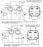
I'll look at the Aikido, but my goal was to build something with the parts on hand (6SN7's, 330V PT, etc.).
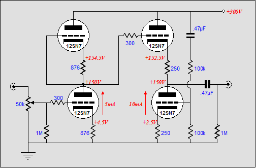
Joel was kind enough to send me this suggestion also.
Glenn
That looks simple also.
I'll look at the Aikido, but my goal was to build something with the parts on hand (6SN7's, 330V PT, etc.).
Joel was kind enough to send me this suggestion also.
An externally hosted image should be here but it was not working when we last tested it.
Glenn
Thank you.
The 12SN7 is the same as the 6SN7 except for the heater voltage, correct?
The tube count is going up then for a stereo version of this circuit (4 tubes).
Glenn
The 12SN7 is the same as the 6SN7 except for the heater voltage, correct?
The tube count is going up then for a stereo version of this circuit (4 tubes).
Glenn
"Joel was kind enough to send me this suggestion also..."
Although I didn't design that PSU. But I do think the direct coupled circuit would be an improvement. It's also simpler.
My gripe about both circuits - and any other RC coupled design used to drive a low impedance like headphones - is that they rely on the load to generate the NFB which improves the linearity. With 100 ohm phones, you essentially have a 6SN7 (or two) with a 100 ohm load. What do you think that's going to sound like?
The fact that a circuit like this sounds almost identical to the headphone amp on the player itself says a lot about the equally poor quality of the solid state version, and even more about the lack of power needed for most 'phones.
There really is only one way to drive a low impedance (probably reactive) load with vacuum tubes, and do it linearly, and that's with a transformer.
Save the cathode follower for buffering a high source resistance.
Joel
- Status
- Not open for further replies.
- Home
- Amplifiers
- Tubes / Valves
- 12AY7/6SN7 preamp PSU check