One thing to keep in mind... You are GROUNDING one side of the power supply... so whatever ripple is remaining is not canceling the tube's filament spiral winding... One approach is to use a + and - rail to the heaters and ground the Center...thus allowing effective ripple (HUM) rejection..
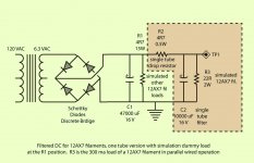
If I model a 3.15VRMS source in LTSpice it gives terrible performance for voltage, under 3VDC. I can assemble the circuit on the bench and see that it puts out over 7 without a regulator. I've attached the circuit.
I like LTspice better than your bench 🙂
3.15Vrms = 4.45Vpeak - 1.3V drop of the 2 diodes gets you 3.25V
Averaging out the ripple component and you get something closer to what LT says than your bench ("over 7").
Some people think that AC is better, but if you do not like hum and intermodulation it is not *that* difficult, with the voltage doubler of post #5 and an LDO regulator to obtain about 1mV of ripple.
Today DC heaters feeding is easier and cheaper than in the 30's, is up to you. 😉
Today DC heaters feeding is easier and cheaper than in the 30's, is up to you. 😉
I think I am getting the clue that 6VDC isn't going to happen without the voltage doubler and honestly it still doesn't look like it will be sufficient. My main confusion is that the circuits from something like a mesa dual rectifier are clearly providing DC from a 6.3VDC tap but it just doesn't add up. I am going to measure the heater voltage at v1 on some of my mesas tomorrow.
I like LTspice better than your bench 🙂
3.15Vrms = 4.45Vpeak - 1.3V drop of the 2 diodes gets you 3.25V
Averaging out the ripple component and you get something closer to what LT says than your bench ("over 7").
Yes once again the math and Sims workout but it's counter to the implementations I've seen. I am thinking it's a popular mistake to multiply 6.3 by 1.414 thinking that it's rms but it's really 2*rms, so our expected DC value should be 4.5 or less.
Last edited:
I think I am getting the clue that 6VDC isn't going to happen without the voltage doubler and honestly it still doesn't look like it will be sufficient. My main confusion is that the circuits from something like a mesa dual rectifier are clearly providing DC from a 6.3VDC tap but it just doesn't add up. I am going to measure the heater voltage at v1 on some of my mesas tomorrow.
If you do not want to use a voltage doubler, from the 6V3 winding, using Schottky rectifiers and an LDO voltage regulator you still can obtain 6V3 DC with slightly more ripple, which in turns is not *that* bad because you can add capacitance and still obtain about 1mV ripple. 😉
That's definitely doable, expecially if you're OK with running the tubes at slightly lower V. They're perfectly happy with 6V, or even a bit less.
A long ago I had the same issue, solved with Schottky diodes, a BiMOS OP-AMP (The old CA3130 working at 5V) and an LM385 voltage reference, it worked just fine clocked at 6V3.
Because spice complains about singular matrices if I don't otherwise provide a reference to gnd ...
Yeah, it happens sometimes. I just use some ridiculously high R, giga or even tera-ohms depending on mood. It also helps other people know it's not real. 🙂
Actually… this device, at $0.90/ea in quantity–10 at Mouser is JUST the ticket:
As little as 0.45 V dropout (awesome!), so my prior calculations come into effect:
Just saying,
GoatGuy
PS: that last bit with Hz, Farads and Amps follows directly from the time-variant response of a capacitor to current flow. The time between full-wave peaks is ¹⁄₁₂₀ Hz (US) or ¹⁄₁₀₀ Hz (most elsewhere). ΔV = 1/C ∫i(t)dt … so at constant I, then IΔt/C equals I/(2CF).
As little as 0.45 V dropout (awesome!), so my prior calculations come into effect:
VDC Peak = √2 × 6.3 VAC
VDC Peak = 8.91 V
VDC rail peak = 8.91 - 2 × VF Schottky drop
VDC rail peak = 8.91 - 2 × 0.55
VDC rail peak = 7.81
VDC rail min = 7.81 - (( 2.1 A ÷ 0.047 F ) ÷ 120 Hz )
VDC rail min = 7.44
The Vmin of 7.44 is WAY above the 6 volt delivery of the above mentioned LDO regulator. They are "only" rated at 1 amp tho', so you'll need 3 of them or so to get the job done. All of $2.70, that is. Tough as nails. And you don't need a post-regulator capacitor for them either. Just reg → filament. VDC Peak = 8.91 V
VDC rail peak = 8.91 - 2 × VF Schottky drop
VDC rail peak = 8.91 - 2 × 0.55
VDC rail peak = 7.81
VDC rail min = 7.81 - (( 2.1 A ÷ 0.047 F ) ÷ 120 Hz )
VDC rail min = 7.44
Just saying,
GoatGuy
PS: that last bit with Hz, Farads and Amps follows directly from the time-variant response of a capacitor to current flow. The time between full-wave peaks is ¹⁄₁₂₀ Hz (US) or ¹⁄₁₀₀ Hz (most elsewhere). ΔV = 1/C ∫i(t)dt … so at constant I, then IΔt/C equals I/(2CF).
Actually… this device, at $0.90/ea in quantity–10 at Mouser is JUST the ticket:
As little as 0.45 V dropout (awesome!) ...
Great! Maybe this help to cure the DC allergy of some folks...
The block diagram suggests that you can put a resistor between the gnd pin and gnd, reducing output voltage using an LF80 for 6V3, what do you think?
I've done some experimenting with filaments and such to reduce noise and hum. Just completed a new 12AX7+12AU7 bass preamp that is extremely quiet (about 60dB down with input loaded). The only thing I did with filaments is raise the DC offset to about 78V to prevent startup arcing because of CF parts. My power supply is bridge rectifier with C-R-C filter - nothing else.
Great! Maybe this help to cure the DC allergy of some folks…
The block diagram suggests that you can put a resistor between the gnd pin and gnd, reducing output voltage using an LF80 for 6V3, what do you think?
Yep, that seems doable. I wish there were a 0.3 VF Schottky diode to put in that position. Mostly current invariant, near-constant voltage (drop) raising potential.
The problem (as found on Mouser) is that the 300 mV VF units are typically so at lots of amps. Great! But … there wouldn't be lots of amps on that to-ground pin. Tops a milliamp or two.
Anyway…
GoatGuy
PS: there is this ... 1N5820G ON Semiconductor | Discrete Semiconductor Products | DigiKey
Which seems to have only a 0.45 VF drop. Maybe at 40 cents, it'd do.
Moreover, since 3 regulators would be needed, ALL of their ground pins could be raised by a single Schottky. Cool, huh?
Last edited:
Actually… this device, at $0.90/ea in quantity–10 at Mouser is JUST the ticket:
As little as 0.45 V dropout (awesome!), so my prior calculations come into effect:
VDC Peak = √2 × 6.3 VAC
VDC Peak = 8.91 V
This is basically where everything breaks down for me. The Tx I am using and what I believe the convention to be for heater taps is more like 3.15VAC RMS which is equal to 6.3VAC CT. So multiplying 6.3 by √2 doesn't seem right, it seems like you would multiply 3.15 by √2 to get the equivalent stable DC value for the same amount of current drain. But I concede to the results not matching my expectations. If I could resolve this factor of two I am off by, I would have a much more thorough understanding of what is happening.
Ignore the centre tap and you have 6.3VAC RMS.
You would have 3.15VAC from end to centre, and so if using the center tap you'd only have 4.4VDC, but when used with a bridge instead of 2 diode full wave, and leaving the centre tap disconnected, you get 8.9VDC. You need to subtract the voltage drop on the diodes, typically 0.7V each. Only two diodes conduct at a time, so 8.9 - 1.4 = 7.5V. Enough headroom for an LDO regulator.
You would have 3.15VAC from end to centre, and so if using the center tap you'd only have 4.4VDC, but when used with a bridge instead of 2 diode full wave, and leaving the centre tap disconnected, you get 8.9VDC. You need to subtract the voltage drop on the diodes, typically 0.7V each. Only two diodes conduct at a time, so 8.9 - 1.4 = 7.5V. Enough headroom for an LDO regulator.
Last edited:
Yeah the 6.3VAC being twice RMS keeps throwing me off, but I get it now. A 3.15V-0-3.15V rms tap is ~9Vpk-pk in reality. I was thinking 6.3VAC was the pk-pk value and there was no reason to think that.
Yep, you're getting it.
Turns out (use Excel to prove it!) if you take sin²() of (say) 360 degrees around a circle, sum it up and divide by the total number of intervals (360!), it equals 0.5 … RMS actually is an acronym for "square Root of the Mean of the Squares", so √(0.5) = 0.707107… or so. So, RMS is 0.707 of PEAK. Peak = 1/RMS = 1/0.707 = 1.414 … equals √(2).
The reason I spec'ed Schottky diodes to build the full-wave bridge is that they have lower VF forward voltage drop. Giving more headroom to the initial capacitor and LDO regulator. I like extra headroom.
Anyway… its all good.
Regulators are good lil' bits of silicon.
LDO regulators are even better.
Good luck!
GoatGuy
I prefer just integrating sin^2 over its period,dividing by that period, then taking the square root. That helps me keep track of the linear properties of whatever I'm (attempting) to analyze because I'd rather use those properties for visualizing the concept. For example, it's easy to see the RMS of a half wave system is 1/2 instead of 1/sqrt(2) by way of the scaling property of that form of the integral. I probably got that habit from doing other transforms.
Sometimes you just make a stupid mistake hahahaha. I will make more.
Sometimes you just make a stupid mistake hahahaha. I will make more.
- Status
- Not open for further replies.
- Home
- Amplifiers
- Tubes / Valves
- 12ax7 with 6.3VDC heater