I have a couple of MerlinB's Compact Phono pcbs stuffed.
I have a Hammond aluminum chassis for the project, 15" L x 7" W x 3" H (38 cm x 19 cm x 7.5 cm)
I'll be using a couple of EI transformers I have on hand.
- For the plate supply (B+) I'll be using the power transformer from a Dyna PAS2 (660VCT 15mA).
- For the heaters I'll be using a separate Radio Shack 12.6VCT 1.2A transformer.
I saw this video which shows how to orient two EI core transformers for least induction.
Transformer Orientation - YouTube
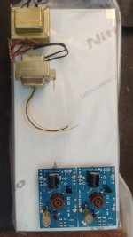
From that, I came up with a basic layout (attached diagram and attached photo).
The idea is to:
1) Keep the audio pcb's as far away from the transformers as possible, and
2) Keep the transformers oriented for least stray field induction into the audio circuitry, and
3) Orient the transformers for least stray field induction into each other.
I don't want to make an external psu connected to an audio chassis by umbilical. I want to make the whole thing in one chassis.
Is this the best compromise to get least hum from this particular collection of parts?
Thanks for any advice.
--
I have a Hammond aluminum chassis for the project, 15" L x 7" W x 3" H (38 cm x 19 cm x 7.5 cm)
I'll be using a couple of EI transformers I have on hand.
- For the plate supply (B+) I'll be using the power transformer from a Dyna PAS2 (660VCT 15mA).
- For the heaters I'll be using a separate Radio Shack 12.6VCT 1.2A transformer.
I saw this video which shows how to orient two EI core transformers for least induction.
Transformer Orientation - YouTube
From that, I came up with a basic layout (attached diagram and attached photo).
The idea is to:
1) Keep the audio pcb's as far away from the transformers as possible, and
2) Keep the transformers oriented for least stray field induction into the audio circuitry, and
3) Orient the transformers for least stray field induction into each other.
I don't want to make an external psu connected to an audio chassis by umbilical. I want to make the whole thing in one chassis.
Is this the best compromise to get least hum from this particular collection of parts?
Thanks for any advice.
--
Attachments

Last edited:
Your transformer is shielded already, not a problem. Just as far away from any sensitive input wires/components.