Hi,
I am currently designing a guitar preamp and before my tonestack I want to put a paralleled 12ax7 (shared plate resistor, shared cathode resistor).
I want to draw my load line for this stage but it seems impossible to find the datasheet for parallel 12ax7. If anybody has it, I would love to see it.
I've checked on many forum and did not find the information I was looking for.
I know that if I 1/2 my resistors the stage would behave like a single triode, but that's not what I want to know, I just want to design and draw my loadline...
Any help would be appreciated!
Thank you
You won't find one. But if you find a data sheet for a 12BZ7 it should be close enough to build from. That tube has double the Gm of the AX7.
Could I just double the plate current on the 12ax7 datasheet and go from there instead of using the 12BZ7 datasheet?You won't find one. But if you find a data sheet for a 12BZ7 it should be close enough to build from. That tube has double the Gm of the AX7.
Care to share a good program to run this simulation my good sir?Easily simulated.

Agree.
You won´t find a dedicated one because it´s not needed: you design for one triode and then halve cathode and plate resistors.
Gain will stay the same, output (internal/generator) impedance will halve , noise will be .707 that of a single triode, which is the only real advantage you will get.
Well, lower internal impedance may also help you if you actually need it.
In fact paralleling lots of same type active gain elements (applies to transistors too) is an old and true way to lower noise, normally used in Radar/satellite receivers and such.
My point is not to have the same gain, so the old halve the cathode and plate resistor is not what I'm looking for. This is the stage that will feed my tonestack so I'm looking forward to have half the impedance primarily and the slight thickening of the tone since no two triode are aexactly the same inside the same tube.
Ty for your repsonse!
Ty for your repsonse!
Nevertheless, designing what you want (including the gain you want) from a single triode loadline then halving the resistors when you double the triodes is what you have to do. There is no other method - apart from guessing.Gui222Gui said:My point is not to have the same gain, so the old halve the cathode and plate resistor is not what I'm looking for.
The famous Marshall 18W has a parallel 12AX7 preamp stage, with a pair of input jacks. One input jack gives you a single triode, while the second gives both in parallel. You get a thicker sound with the parallel input.
I want to draw my load line for this stage but it seems impossible to find the datasheet for parallel 12ax7.
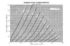
Consider a single 12AX7 with twice the plate resistor and twice the cathode resistor as your circuit.
By the bisection theorem, the voltages are the same as in your circuit, so you can then use the
standard curves for one section to plot the load line. Of course, the power supply still has to give
the full current, and the stage's output impedance will be half.
Last edited:
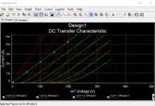
On the plate curves, just double the values of the plate current (Ip) scale and you are !
And here is exactly the same dichotomy I have run into, many times, all over the Internet.You get a thicker sound with the parallel input.
Mathematically, assuming the two triodes in a 12AX7 are identical, Yves is clearly right. Paralleled triodes should have exactly the same transfer function (anode curves), with gm and Ia doubled at every point.
And if the curves are the same shape, the mathematics of the Fourier transform tells us that they should produce exactly the same harmonic distortion spectrum. Which means paralleled triodes should sound exactly the same as a single triode (operated at the same Vgk and Va, and half the Ia).
And yet, many, many, people claim that parallel triodes sound different from single ones.
I have only ever found one set of actual objective measurements comparing single and parallel triodes. They were the work of one Steve Bench, a gifted electronic designer who had an Internet presence in the late 1990s and early 2000s. Bench's measurements did show some measured differences between single triodes and nominally identical, paralleled, ones.
Here is Bench's measurement of a single triode:
http://www.jacmusic.com/techcorner/SBENCH-PAGES/sbench102/d_ax7_1.gif
And here, his data for paralleled triodes: http://www.jacmusic.com/techcorner/SBENCH-PAGES/sbench102/d_ax7_3.gif
(I've attached those two images to this post, as well.)
You can see that the two sets of distortion spectra Bench measured, are, in fact, not the same shape at all. The 2nd harmonic curves, for example, have a significant dip at 30 V rms in the case of the single triode; that dip is virtually non-existent for the parallel triodes.
I think what we're seeing is the reality that the two triodes in one 12AX7 bottle are never, in fact, exactly identical. This means they will have slightly different transfer curves, and therefore, produce slightly different harmonic spectra at any given level of signal drive.
Those two slightly different spectra will be summed together at the paralleled anode, and the the resulting sum will not be exactly the same as either individual spectrum by itself.
And it's the summed spectrum that we hear (or see, in Bench's measurements.)
This means any supposed benefit (improved distortion quality) occurring from paralleled triodes is a complete and utter roll of the dice, depending as it does, on the statistically random slight differences between the two triodes in one 12AX7 envelope. There is little chance that any two 12AX7s will produce the same results when paralleled.
I would say therefore, that paralleling triodes in the hope of getting improved sound, falls into the category of gambling, rather than good engineering practice.
I haven't discussed noise performance here - that is the only solid engineering reason for paralleling triodes (or transistors, or FETs). Paralleling multiple devices can produce improved signal to noise ratios (gain goes up more than noise voltage does, so S/N ratio is improved).
-Gnobuddy
Attachments
Paralleled triodes should have exactly the same transfer function (anode curves),
with gm and Ia doubled at every point.
Paralleled triodes will also have twice the Miller capacitance, which is significant for 12AX7s.
Last edited:
Good point, so the high-frequency responses may look a bit different.Paralleled triodes will also have twice the Miller capacitance, which is significant for 12AX7s.
In a guitar amp, I suspect the guitar cable capacitance will still dominate. Typical input capacitance for one triode from a 12AX7 seems to be roughly 100 pF, so about 200 pF for a paralleled pair set up for the same voltage gain.
Meantime, typical guitar cables seem to have between 50 pF and 150 pF per metre*, so a typical 5-metre cable will have between 250 pF and 750 pF of total capacitance.
* Guitar Cable Capacitance Chart ? Comparison of pF Ratings by SHOOTOUT! Guitar Cables UK
-Gnobuddy
Parallelled triodes in simulation will look the same as one triode with twice the gm and half the ra. In reality, as Gnobuddy says, they will not be identical so distortion will be different and unpredictable. However, one might expect this to be a small effect unless a poor bias point is deliberately chosen.
Easily, for ideal case, like most people here pointed.Easily simulated.
For simulating real case, one needs to manipulate rp, µ and gm for each device, for finding transfer curves more like reality. Eg.: one element with µ=105 and other with µ=95, and corresponding gm and rp variants (creating new Spice models, for example). Like late DF96 and Gnobuddy said, this is unpredictable in real life but yes we can simulate a hypotetical case and see the resulting mathematical transfer.
- Home
- Live Sound
- Instruments and Amps
- 12ax7 in parallel datasheet