Hey, sorry to bring this up again. I know it's not exactly a new topic, but in my searches I've read some contradictions among those I would probably consider experts.
In short, does the grid-stopper resistor load the pickup? I don't see how. I can see how a grid LEAK resistor does, but not the grid stopper. It seems the two are often exchanged in discussion with disregard.
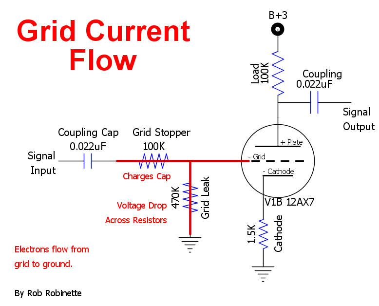
For reference, these are the resistors in question:
Honestly, I want to lower the grid STOPPER resistor to something like 10k or lower, and use a cap in parallel to cutout frequencies higher than audio. I don't see how this is an issue if there's a grid LEAK resistor in the circuit. Of course, a grid leak resistor AFTER the STOPPER makes a voltage divider, so that would have to be considered.
In short, does the grid-stopper resistor load the pickup? I don't see how. I can see how a grid LEAK resistor does, but not the grid stopper. It seems the two are often exchanged in discussion with disregard.
For reference, these are the resistors in question:
An externally hosted image should be here but it was not working when we last tested it.
Honestly, I want to lower the grid STOPPER resistor to something like 10k or lower, and use a cap in parallel to cutout frequencies higher than audio. I don't see how this is an issue if there's a grid LEAK resistor in the circuit. Of course, a grid leak resistor AFTER the STOPPER makes a voltage divider, so that would have to be considered.
You can do that either way, it depends. What cutoff frequency do you want?
The grid stopper does load the pickup, but mainly above the LP corner frequency,
or else above the frequency that the MIller effect capacitance forms a LP with the stopper.
A 10k or less is a typical stopper value, except for a musician's amp.
It maybe be best to have an RC LP filter, and then the grid stopper, for RF interference reasons.
Last edited:
I would put the grid stopper right on the socket and no it does not present any load there. 10K is fine. If you want to cut high frequencies, put a cap across the the plate R, 100pf to 1000pf would be a bracketed good starting point
The stopper is to stop oscillations at RF frequencies, it goes right on the grid (the higher bandwidth the tube, the more important this is). Its ideal value isn't trivial to determine, follow the advice in datasheets if available. It should be a non-inductive type or you defeat the purpose.
Any connection of a cap direct to the grid will bypass the stopper and render it useless, so don't do that, use a separate RC low-pass section if wanted.
Any connection of a cap direct to the grid will bypass the stopper and render it useless, so don't do that, use a separate RC low-pass section if wanted.
The grid stopper there is the wrong side of the 470k resistor.
As it stands its attenuating input signal.
As it stands its attenuating input signal.
As already was written, grid stopper might be connected between grid and grid resistor. I use mostly 1k-10k, depends on value of Cg/Cg1. If you want to add another C, connect it paralelly to grid resistor.