hi
I want to build a class a1 amplifier with 2a3, however I don't understand why half 12ax7 tube is never used as a tube stage driver.
according to my calculations to make a 2a3 work at full power you need 30 vpp on the grid that with a half of 12ax7 (with a gain of about 100) I should be able to obtain with about 300 mVpp (100 mV rms) in input
why for the driving of these tubes (2a3, 300b) we always see "strange" drivers like srpp, parallel triode, cathode follower and not a trivial amplifier stage with only one tube?
I think the reason why other tubes are used in a 2 stage design is simply that they sound better. But also that you can put more current through them, so you get better drive to the outputs.
If you have reasonably sensitive speakers you need a tube with around mu = 30. More sensitive speakers could probably use an E80CC even. Go up to mu = 40 and you find some of the favourite drivers like C3g in triode. And then on up to several pentodes in triode like EC8010, E180F, E280F, E810F, EF184, 6e6P, 6e5P, D3a. Simple circuits using triodes as drivers. The only thing you have to reckon on is paying close attention to the tube socket so you don't get oscillation from some of these high gm tubes.
You can load the driver stage with a resistor or a plate choke. Plenty of cheaper plate chokes like Hammond 157G which sounds pretty good and is used in Hagerman gear. No need for anything more complex, though it's fun to experiment and devise clever circuits.
.
Last edited:
It's been discussed to death ....
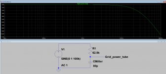
Power tube Miller capacitance, required grid swing, driver tube output impedance, driver tube anode current....
If the first and second is in the high side, and the third large, fourth small, another drive tube must be chosen.
Attachment: 12AX7 driving 2A3 Miller capacitance
Power tube Miller capacitance, required grid swing, driver tube output impedance, driver tube anode current....
If the first and second is in the high side, and the third large, fourth small, another drive tube must be chosen.
Attachment: 12AX7 driving 2A3 Miller capacitance
Attachments
Last edited:
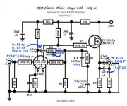
IMO, the device to buffer wimpy types, like the 12AX7/ECC83 & EF86, is the ZVN0545A enhancement mode MOSFET. DC coupling that part to the voltage amplifier's plate is a "no brainer". The provided tweaked RCA phono preamp illustrates the method. Experience has shown that a 12 V. protective Zener diode should be connected between the plate side of the gate stopper resistor and the FET's source electrode.
Attachments
It's been discussed to death ....
Power tube Miller capacitance, required grid swing, driver tube output impedance, driver tube anode current....
If the first and second is in the high side, and the third large, fourth small, another drive tube must be chosen.
Attachment: 12AX7 driving 2A3 Miller capacitance
very helpful, thanks a lot, so if i undestand i can use an ecc99 (with an internal resistence of 2,3k) to drive the 2a3 tube well because the hypothetical low pass filter have a very high cutoff frequency (aprx 650khz)
or another solution is the implementation of an interstage transformer like hammond 126a with an half of a 6sn7 to drive the grid with a imedence of 5k
Last edited:
lorenzo01,
First consider a few things:
1. The bias voltage you will have on the 2A3.
Typical bias of 45 to 50V (50V on the Baby Ongaku).
At 50V bias, the driver needs to be capable of 35Vrms (50V peak).
2. The signal source.
A CD player typically has 2.1Vrms (3V peak), at full scale.
50V/3 = 16.7, the minimum required driver gain to get full output from the 2A3.
Few CD recordings ever reach full scale output, so you may want more gain than that.
If you use an IXYS constant current source for the plate load, the major load on the driver stage is the 2A3 grid resistor; you will get gain almost as high as the triode u (Mu).
Try using an ECC99 (u = 22), 12AY7 (u = 40), or a 12AT7 (u = 60).
All of those will work well with the IXYS current source plate load.
However, if you are going to work with the 3V peak from the CD player, each of those tubes will need to be biased at at least -3V grid to cathode, in order to have the excess gain used for low output CD recordings (Some Chesky CDs are about -10, -15, or -20dB on the loudest parts of the recordings).
But with some CD recordings that have almost 3V peak out, that is why I did not mention the 6DJ8 for example. It will not be linear with -3V bias, and the grid swinging from 0V to -6V (very non linear at -5 and -6V).
Even the 12AT7 will struggle a little with the bias at -3V, and the peak signal taking the grid to -6V).
The same goes for the 12AY7, but the gain of 40 will make up for that (does not need 3V peak signal, use a volume control).
Yes, with proper design, you can use a 12AX7, but it does not have enough current to run an IXYS part properly, you could use a discrete current source for the plate load.
Since the 12AX7 has enough gain, the bias does not have to be -3V, it can be more like 1 or 1.5V, and a volume control to the grid, will work for 3V peak from the CD.
Euro21 shows the frequency response of the 12AX7 that is about -1dB at 20kHz when driving a 2A3.
Well, do you care about -1dB at 20kHz?
I do not, I can only hear about 13kHz.
And, if the idea of -1dB at 20kHz bothers anybody, then even with a perfect amplifier, they had better listen to their tweeter dead on axis.
Most tweeters will be more like -2dB or -3 dB at 15 degrees off axis.
So now, the next problem is that with the 2A3 Miller capacitance loading the 12AX7 will cause harmonic distortion, at say 10kHz and above.
Wait a minute! the 2nd harmonic of 10kHz is 20kHz, and many of us do not hear that.
Yes, with a 12AX7 and 2A3 giving -1 dB at 20kHz, and an output transformer -1 dB at 20kHz, and a tweeter -1 dB at 20kHz, the total response will be -3dB at 20kHz.
When is the last time you had your ears tested to 20kHz? How many dB down were they?
Make it as complex as you want, or keep it simple.
the ECC99 and IXYS current source plate load sounds like a good solution.
Peel the outer layers off of the onion first, before worrying about the inner layers of the onion.
Happy designing, happy building, and happy listening.
Last edited:
Hi
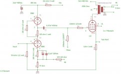
in attach a good stage, simply and very easy to build with a E88C , very good tubes at reasonable prices, it is easy to find Siemens gold pin
Great swing, reasonble thd and reasonable low Zout
It drives a KT150 but is fine for 2A3
Just to arrange the Vdc and bias point
In addition the response of this circuit at 20 volt out
With 450 mV in you got 20 Vout rms.
The clipping is more than 40 Vrms
Walter
Attachments
SRPP, Cascode, and similar totem pole stages . . .
Be sure to elevate the filament voltage, the DC quiescent and peak swing may exceed the maximum filament to cathode ratings.
And, AC filament leakage to the cathode of some tubes may cause hum.
Find a tube that does not hum there.
Simple, or complex. Again a tradeoff.
And, if you use a low output signal source, such as a phono preamp (not a CD player),
You may need a high gain driver.
Last edited:
12ax7 drives 2n5551 ksc1845 ksc3503 well past 20khz with lower distortion then a mosfet. Especially a irf820 power fet which is working in the cutoff region.
SRPP, Cascode, and similar totem pole stages . . .
Be sure to elevate the filament voltage, the DC quiescent and peak swing may exceed the maximum filament to cathode ratings.
And, AC filament leakage to the cathode of some tubes may cause hum.
Find a tube that does not hum there.
Simple, or complex. Again a tradeoff.
And, if you use a low output signal source, such as a phono preamp (not a CD player),
You may need a high gain driver.
Where is the problem?
I think who is playing with these type of circuit knows well what is necessary to do.
And the selection of tube is alway suggested.
Never got problems of hum in this type of circuit.
This circuit is not for phono preamp, it needs a preamp as you can understand.
Walter
...make a 2a3 work at full power you need 30 vpp on the grid ...
"vpp" is Peak-to-Peak?
I figure (from data sheet) about 45V peak or 90V peak-to-peak.
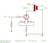
On thumbs, I figure a healthy voltage-amplifier tube can make a peak swing of about 20% of the supply voltage. Or B+ must be 5X the peak swing needed. Or: we want 45V peak. We need 225V of supply. Not a big problem since the 2A3 needs 250V-300V of supply. However the 12AX7 swinging 45V peak with 300V supply will be around 4% THD. This cancels the 2A3 distortion, incompletely.
In self-bias, our B+ is higher (more food for the driver) and we may use the 500k grid-leak which a 12AX7 laughs at.
I make the Miller+grid near 60pFd, call it 100pFd. So the "500k" falls above 6.7kHz, above most of the power in speech/music. The equivalent source of a 12AX7 with popular load and bias is near 39k. Small-signal response may be -3dB@80kHz, -1dB@40kHz, -0.5dB@20kHz.... much better than most transformers.
The bypassed gain of 12AX7 is near 50, so 45V peak output, 30V rms, needs 0.6V rms input. This is rather low for DAC sources. No-bypass gets gain down to half and input sensitivity near 1.2V rms, but also raises plate resistance lowers high frequency roll-off point.
But don't do it. It is not cool to use a guitar amplifier tube with a movie theater tube.
Attachments
The use of 12AX7 in this type of circuit is not a good solution.
The only solution that works fine with this tube to drive a power tube with a large swing and low Zout is a Gomes topology
The Gomes use 12AX7 to drive a 211 in p-p but this is another story
Walter
The only solution that works fine with this tube to drive a power tube with a large swing and low Zout is a Gomes topology
The Gomes use 12AX7 to drive a 211 in p-p but this is another story
Walter
Attachments
"vpp" is Peak-to-Peak?
I figure (from data sheet) about 45V peak or 90V peak-to-peak.
On thumbs, I figure a healthy voltage-amplifier tube can make a peak swing of about 20% of the supply voltage. Or B+ must be 5X the peak swing needed. Or: we want 45V peak. We need 225V of supply. Not a big problem since the 2A3 needs 250V-300V of supply. However the 12AX7 swinging 45V peak with 300V supply will be around 4% THD. This cancels the 2A3 distortion, incompletely.
In self-bias, our B+ is higher (more food for the driver) and we may use the 500k grid-leak which a 12AX7 laughs at.
I make the Miller+grid near 60pFd, call it 100pFd. So the "500k" falls above 6.7kHz, above most of the power in speech/music. The equivalent source of a 12AX7 with popular load and bias is near 39k. Small-signal response may be -3dB@80kHz, -1dB@40kHz, -0.5dB@20kHz.... much better than most transformers.
The bypassed gain of 12AX7 is near 50, so 45V peak output, 30V rms, needs 0.6V rms input. This is rather low for DAC sources. No-bypass gets gain down to half and input sensitivity near 1.2V rms, but also raises plate resistance lowers high frequency roll-off point.
But don't do it. It is not cool to use a guitar amplifier tube with a movie theater tube.
Agree!!!!!
Walter
Quote,
waltube: I think who is playing with these type of circuit knows well what is necessary to do.
If that were the case, we would not have newbies asking questions, such as:
"why am I having problems with my SRPP?"
"Why is there hum in my Concertina?"
(Newbies are known to put together circuits that do not work. They just copy what they see from a schematic, that is either not good, or is incomplete, with no details such as floating filaments).
The worst commercial tube amplifier I had was a poor design, and that had hum that would have easily been fixed by a little more attention to detail. Back then I did not have the knowledge to fix it.
I had simpler amplifiers that worked better than it did.
Hi
in attach a good stage, simply and very easy to build with a E88C , very good tubes at reasonable prices, it is easy to find Siemens gold pin
Great swing, reasonble thd and reasonable low Zout
It drives a KT150 but is fine for 2A3
Just to arrange the Vdc and bias point
In addition the response of this circuit at 20 volt out
With 450 mV in you got 20 Vout rms.
The clipping is more than 40 Vrms
Walter
I don't believe NBF is required for an SRPP. The load line should be pretty flat already....
to mooreamps
I can't understand.
The global feedback in the circut is only 6dB and the purpose mainly is to lower the Zout of the amp, that is always better
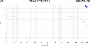
In attach the response of the amp.
And the THD vs freq. with two bias current.
Of course you can't use the NFB and get always a reasoble results
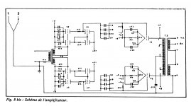
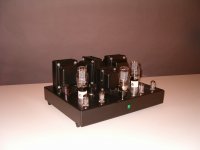
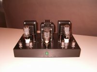
Also in attache a old project I done in the past with 2A3
And the schematic the input is a Gomes circuit with 6N1P
The 2A3 was Sovtek, very fine, biased at 90% of max power.
It is running since 2008 without problems
I have also all lab test
I can't understand.
The global feedback in the circut is only 6dB and the purpose mainly is to lower the Zout of the amp, that is always better
In attach the response of the amp.
And the THD vs freq. with two bias current.
Of course you can't use the NFB and get always a reasoble results
Also in attache a old project I done in the past with 2A3
And the schematic the input is a Gomes circuit with 6N1P
The 2A3 was Sovtek, very fine, biased at 90% of max power.
It is running since 2008 without problems
I have also all lab test
Attachments

to 6A3
In general I am agree with you but the solution is always , IN CASE, proprose always the schematic with test lab as certification ( and of course the assembled parts)
This is the only way, in may opinion to give a right indication
Too many simulation with strange configuration that never put on the table in the lab
Walter
walltube,
In terms of simulation, I agree.
I remember Bob Pease, who authored Pease Porridge column in EDN magazine, who more than once talked about simulation versus reality.
And I remember his article on an early vacuum tube Op Amp.
If I think of a batch of JFETs that has a spread of 3:1 IDSS, there is a good example of simulation inaccuracy versus process control (sorry for the temporary crossover to solid state parts).
Test results of real amplifiers (measurements with resistive loads; and listening on various kinds of loudspeakers are strong contenders for the truth).
Then, when the listening tests begin, remember that different people have different systems that surround the amplifier (signal source, loudspeakers, room, and types of music that are preferred) . . .
I remember when Tubelab_com told about designing and building a batch of amplifiers that had an unlabeled negative feedback control.
He gave them to coworkers and others to use and listen too.
They were told to adjust the control according to what sounded best to them (but not told what they were adjusting).
The interesting thing was that there were mostly only 2 general setting areas.
One was lots of negative feedback.
The other was either moderate negative feedback or no negative feedback (I do not remember which).
Listener preferences can be a surprise.
Last edited:
- Home
- Amplifiers
- Tubes / Valves
- 12ax7 as a driver stage for 2a3 tube amplifer