In a prototype configuration, I have an actively equalized RIAA phono stage. It has two cap coupled 12AX7 mu followers cap coupled to a cathode follower.
I want to eliminate the CF if possible. A 12AX7 mu follower probably will not perform an adequate job of driving a 10k load (10k or higher is the requirement). What about using a 12AT7 as the second stage? The goal is 40dB gain or more. So far it is 40 and spice reports a dB or two less (basically the same) with a 12AT7.
I want to eliminate the CF if possible. A 12AX7 mu follower probably will not perform an adequate job of driving a 10k load (10k or higher is the requirement). What about using a 12AT7 as the second stage? The goal is 40dB gain or more. So far it is 40 and spice reports a dB or two less (basically the same) with a 12AT7.
I would use an EF86 and an ECC83 all with lots of negative feedback to get rid of any noise. ECC83;-
ECC83 is a slightly higher spec. 12AX7.
A pair of 6n3P-E's would be good, (ECC42).
ECC83 is a slightly higher spec. 12AX7.
A pair of 6n3P-E's would be good, (ECC42).
I would use an EF86 and an ECC83 all with lots of negative feedback to get rid of any noise.
Wait, what?
Yeah, what do you mean? I don't think your idea will work unless there is something in your mind that is not being communicated.
OK, here is the story. I settled on a 12AX7 12AY7 combo. It is giving me all the RIAA gain I need and then some.
The unit sounds very good. I currently am listening to an Eddie South jazz record in mono over my test speaker. Very crisp clear audio and dynamics. Over the past couple days I tried a cascode. I also tried the same configuration as now only with two 12AX7 tubes and a cathode follower. Both trials sounded so dead compared to the configuration I have now, especially the cascode. The cascode sounded so compressed, dead, and transitory.
I am having a problem with my woofer dancing at an irregular frequency when the volume is all the way open. I tried a few combinations, even an active regulator. The active regulator seems to temper it a tad, but not eliminate it. I do not want to use an active regulator unless I absolutely cannot help it. What should I do to temper this bounce? Is it just low frequency white noise and a normal part of high gain circuitry? The schematic is attached. I only have one channel built for debugging purposes.
What do you think of the design in general? It sounds so sweet to my ear.
Attachments
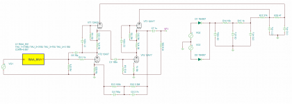
I'm puzzled by C6 - you will get huge Miller capacitance from this. This will make it difficult for the inverse RIAA network to deliver the correct result unless it contains a virtual buffer.
At present your dominant LF rolloff is the output cap. 3Hz with 50k loading. 15Hz with 10k loading. This could mean that serious subsonics could already have caused IM in the preamp before being filtered out. There are two main sources of subsonics: mains voltage variation, record warps. I would add an input coupling cap to reduce the latter.
Given that the main loop has an LF rolloff somewhere around 1Hz you will get problems. You have three identical time constants: C1R3, C3R10, C2R8. This could mean a lot of phase shift around the 1.6Hz region. You might even get a response peak! Have you looked down here?
The whole supply arrangement is nowhere stiff enough at subsonic frequencies so is likely to lead to motorboating or nearly so. I guess the big resistors are to drop voltage. Not a good idea for an RIAA preamp with high LF gain.
Attacking very low subsonic frequencies will involve insane amounts of capacitance in the power supply.
What I have in mind to stop this problem.
Change out R10 in spice for a 100k ohm. The subsonic rolloff is much more steep but the gain in the motorboat zone is still high (around 15 or so DB). Should it be lower?
Make the capacitors in the power supply 100uF. The large resistors are to drop voltage. Should I use smaller ones?
You can't get big enough PSU caps to stop subsonic problems. The issue is that you have isolated the PSU output from the clamping effect of the rectifier by using big resistors. Get rid of them, or at least use much smaller resistors. Use a choke or regulator if you need less hum. Ensure that the two stages have supply rails which are as independent of each other as possible; otherwise the PSU becomes a feedback path.
Reducing the value of R10 or C3 may help.
You still need to identify the source of the subsonics: mains changing, near motorboating, record warps? First identify the problem, then fix it.
Reducing the value of R10 or C3 may help.
You still need to identify the source of the subsonics: mains changing, near motorboating, record warps? First identify the problem, then fix it.
The unit has the subsonic anomalies when there either is no turntable or there is a turntable connected (should have been more clear here) and no record is playing. I see the woofer moving as if it is being tickled in a random pattern, not at a constant frequency. I revised the circuit as follows (see schematic).
After probing with the scope I found an RF oscillation at 1.53 MHz. Placing a 39pF cap between the plate and cathode of VT2 changed it by lowering the amplitude and upping the frequency to 4.7 MHz. The 4.7 MHz RF noise disappears when the turntable is disconnected. 1K Grid stoppers were added but did not affect the oscillation. I have a feeling I should add a low pass filter somewhere else to kill this as the 39pF cap does not cut it. Should I up the value or place a low-pass filter somewhere in the loop? RF noise can radiate and cause interference, which is not good.
As for the woofer bounce, changing the power supply, C3, C7, R12, and R3 helped temper the tickle bounce but did not eliminate it. There is hum and hiss too that is around typical of phono stages. What do you recommend in scrubbing away the remainder of the bounce and attacking the hum and hiss? I have a feeling some of is coming from the RF anomaly.
Use a regulated supply (don't forget the heaters! Are V1/V3 heaters elevated enough to avoid stressing Vhk?) and severely decouple the two stages. Stagger the zeros. This should take care of the LF issues.
The HF issues are (I would guess) due to some layout problems and unintentional poles from stray capacitance. A few step networks to roll off the HF open loop gain may be useful- essentially, you have to design this to be unity gain stable.
The HF issues are (I would guess) due to some layout problems and unintentional poles from stray capacitance. A few step networks to roll off the HF open loop gain may be useful- essentially, you have to design this to be unity gain stable.
Think of the Bode plot- if you stack the zeros (that is, have too many of them too close together), the closed loop gain line will intercept the LF side at a point where the rolloff is steep. Bingo- instability. If you keep the zeros well-separated, the intercept is likely to be at a place where the rolloff slope is less than 12dB/octave and will thus be stable.
Somewhat unusually, this seems to be feedback loop RF instability. Add a CR lead-lag compensation network (some people miscall it a snubber) to VT2 anode. This is a high impedance point, so quite a small cap may do it. Scrap C6, as it simply imposes a huge input capacitance.kingneb said:After probing with the scope I found an RF oscillation at 1.53 MHz. Placing a 39pF cap between the plate and cathode of VT2 changed it by lowering the amplitude and upping the frequency to 4.7 MHz. The 4.7 MHz RF noise disappears when the turntable is disconnected. 1K Grid stoppers were added but did not affect the oscillation. I have a feeling I should add a low pass filter somewhere else to kill this as the 39pF cap does not cut it. Should I up the value or place a low-pass filter somewhere in the loop? RF noise can radiate and cause interference, which is not good.
That suggests the subsonic input source is mains voltage variations. Two solutions: reduce subsonic gain, add a voltage regulator.I see the woofer moving as if it is being tickled in a random pattern, not at a constant frequency.
Is the lead-lag a network a CR network from the anode to ground? I have been messing around with a configuration from the VT1 cathode to the VT2 anode, which does nothing.
Yes, CR from anode to ground.
Something else to try is turning the first stage into a simple active load - move C3 from VT1 cathode to VT2 anode. This will then use the Miller capacitance of the second stage combined with the anode impedance of the first stage to insert a dominant HF pole. Mid-band gain and distortion will be almost unchanged.
Something else to try is turning the first stage into a simple active load - move C3 from VT1 cathode to VT2 anode. This will then use the Miller capacitance of the second stage combined with the anode impedance of the first stage to insert a dominant HF pole. Mid-band gain and distortion will be almost unchanged.
Seems like a 1.5k and 220pF cap killed the RF oscillation. Lets see if it stays that way. Now time to work on my MATLAB project, then tackle the subsonic issue.
A quick calculation suggests that will start reducing open loop gain from 12kHz. Sounds OK to me.
- Status
- Not open for further replies.
- Home
- Amplifiers
- Tubes / Valves
- 12AX7 / 12AT7 Mu Follower Phono