12AU7 and 6CG7/6FQ7 are not quite the same, and datasheets should show this. Different mu, different gm. My understanding is that a 6CG7 should always have an internal shield, and a 6FQ7 should not have a shield, but manufacturers often label a 6CG7 as 6CG7/6FQ7.
That's right. 6CG7 and 6FQ7 both are derivatives of the good old octal 6SN7 GTB - same data, different packages. Who would seriously claim that 6SN7 and 12AU7/ECC82 share their data? Best regards!
I ran quite a few vintage 6SN7 and 12AU7 through the same common cathode PP driver stage (in a Williamson without feedback or output stage valves), and for 10Vrms signal on each plate, the 12AU7's generated about twice the 2nd harmonic (about 0.8%) as the 6SN7's (0.3-0.4%). 2nd harmonic distortion component was dominant by at least about 20dB.
Yes. It is the strong dominance of 2nd for 12AU7 which makes them excellent in balanced situations, as the 2nd cancels. It also makes them good high dynamic range radio receiver mixers!
A bit about methods
Hello Merlin(b),
Thank you for your recommendation for noise measurement bandwidth; it will be 20Hz – 20KHz. The handle of the hockey stick will just be a bit extended.
I am concerned about power line frequencies and switching frequencies from my bench power supply creeping in. I am putting together a C-L-C added filter for the power supply.
A bit about methods;
With the “12AU7” in the test circuit and a Hamm window FFT on the QA401 analyzer the current through the test “12AU7” will be twiddled for the lowest FFT calculated RMS across 20 – 20K BW. Data will be recorded in a spreadsheet and a FFT saved to file.
The current value with the lowest noise will be the target value for subsequent distortion testing.
Additions? Exceptions?
I will test drive the C-weighted filter in the AP2522.
DT
Valve noise is normally dominated by 1/f noise, so there is not likely to be much difference between C-weighting and unweighted (20-20kHz) measurements. In which case I would encourage you to use unweighted measurements as they are more universally useful to anyone you care to share the numbers with.
Hello Merlin(b),
Thank you for your recommendation for noise measurement bandwidth; it will be 20Hz – 20KHz. The handle of the hockey stick will just be a bit extended.
I am concerned about power line frequencies and switching frequencies from my bench power supply creeping in. I am putting together a C-L-C added filter for the power supply.
A bit about methods;
With the “12AU7” in the test circuit and a Hamm window FFT on the QA401 analyzer the current through the test “12AU7” will be twiddled for the lowest FFT calculated RMS across 20 – 20K BW. Data will be recorded in a spreadsheet and a FFT saved to file.
The current value with the lowest noise will be the target value for subsequent distortion testing.
Additions? Exceptions?
I will test drive the C-weighted filter in the AP2522.
DT
Attachments
Last edited:
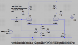
Hmmm... Why would the simulation show such drastic differences in distortion from the inverting and non-inverting outputs?


Never mind longer tail and higher B+ gives much closer results (however HD2 not as low as the non-inverting was with the shorter tail). More investigation called for.
Never mind longer tail and higher B+ gives much closer results (however HD2 not as low as the non-inverting was with the shorter tail). More investigation called for.
Attachments
Last edited:
Put a constant current sink in place of R5 and see what happens to your harmonic distortion results. 🙂
Looking at the circuit, the operating conditions for U1 and U2 are completely different; plate voltage, plate current, plate resistor, grid to cathode voltage. U2 grid in terms of AC is bypassed by C3 making U2 cathode input. U1 uses the grid for input. The only thing that UI and U2 have in common is cathode voltage.
The difference in distortion performance is not too surprising.
DT
The difference in distortion performance is not too surprising.
DT
To get identical performance at the two outputs you need perfectly matched triodes (you get these for free in simulation), identical circuits on both sides (e.g. bias arrangements, anode load), and perfect balance.
Two ways to get perfect balance:
1. feed antiphase input signals to both grids (then the tail does not matter)
2. use an infinite tail impedance and AC ground one grid.
Two ways to get perfect balance:
1. feed antiphase input signals to both grids (then the tail does not matter)
2. use an infinite tail impedance and AC ground one grid.
Not necessarily. If the tail's impedance is indeed infinite and the anode resistors identical, you can use a 12ax7 for one half and a 12au7 for the other. The (AC) symmetry will still be perfect, at least at low frequencies.To get identical performance at the two outputs you need perfectly matched triodes
All that is of course theoretical and assuming no additional load at the anodes.
Last edited:
Already covered byKay Pirinha said:...3. and equal plate resistors!!!
DF96 said:identical circuits on both sides (e.g. bias arrangements, anode load)
OK. The more similar the triodes and the higher their mu, the less sensisitive is the circuit to tail impedance - so 12AU7 is a bad choice for a resistor tail. The better tha tail, the less do the triodes have to match - but two different triodes will tend to give results dominated by the 'weaker' one in gain terms.Groucho2004 said:Not necessarily.
A good way to consider the LTP phase splitter is to think about common mode gain and differential mode gain. Differential mode gain is essentially the same as for a grounded cathode circuit, so is a bit less than mu. Common mode gain is like a cathodyne, set by the ratio of the cathode and anode resistors. Hence the ratio of the two gains (which sets output balance when used with a single-ended input) is maximised by high mu and high tail resistance. Fortunately common-mode input produces common-mode output, which a PP output stage will largely ignore. Hence people have been able to get away with using low mu valves like 12AU7 and 6CG7 as LTP phase splitters with a resistor tail even though the performance will actually be poor.
Already covered by
Sorry 'bout my ignorance. But as you perhaps might know, English is not my native language.
Best regards!
Of course the different size plate resistors are because of the finite tail. But increasing the tail to 27k and the B+ to 300v gave much better results. Looking at this as an opportunity to put the bunch of 12AU7s I have to good use and make a decent low gain preamp without dumping a lot of cash into it.
If the tail's impedance is indeed infinite and the anode resistors identical, you can use a 12ax7 for one half and a 12au7 for the other. The (AC) symmetry will still be perfect, at least at low frequencies.
Somewhere else in this board it has been shown that even a LTP with such very different triodes as half a 12AX7 and half a 6922 provides perfect AC balance, if the tail is a CCS with virtually infinite impedance, and the plate loads are equal, of course.
Best regards!
The math is very simple. If the ccs in the tail is ideal, the absolute value of a current change in each valve is identical (assuming no current flow in the grid circuit).Somewhere else in this board it has been shown that even a LTP with such very different triodes as half a 12AX7 and half a 6922 provides perfect AC balance, if the tail is a CCS with virtually infinite impedance, and the plate loads are equal, of course.
In practice, grid current or - more prominent at higher frequencies - grid currents caused by Cag/Cgk will upset that balance.
Disappearing 3rd Harmonic
Hello All,
I don’t go back to school until Monday next week and I have finished my honey do list.
I have some time to play with my toys on the bench.
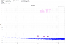
I set up a breadboard with a Common Cathode circuit using a PhillipsECG 5814A. There is an adjustable 0-15 Volt supply for the heater, a Keysight N5752A 0-600 Volt supply for the B+. I added a C-L-C Pi filter to remove a little more of the line frequency ripple. The anode resistor is 15K, the 300 ohm cathode resistor is bypassed and there is a 300 ohm input resistor. Oh yes there is a 1 Meg ohm grid bleed resistor.
I started out turning up the B+ supply voltage and measuring the delta V across the cathode resistor so I could track current in 0.5 mA steps. After figuring the B+ supply voltage steps I hooked up the AP 2522 analyzer and started measuring noise.
This one tube over the BW of 100 Hz to 22KHz (Merlin, the C-weighted filter measured very close) performed best at near 10 mA, or ~ 1.2 uV EIN. This is just getting started more EIN measurements to follow.
While I was at it I looked at FFT’s. Setting the input voltage for 2.0 Volts at the output, the gain calculated out to be 13.25.
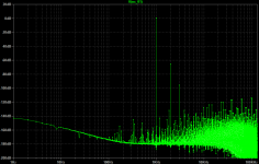
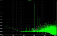
Does anyone recall the George Fletcher Cooper paper (another guy published the very same information, who copied the other?) that adjusted the cathode resistor value to null out the 3rd harmonic. I came across the same thing by adjusting the supply voltage while running FFT’s.
It was a real ah ha moment when I saw the 3rd Harmonic disappear from the FFT plot the first time.
See the attached plots.
The first plot was run at 233 Volts B+.
The second plot was run at 339 Volts B+.
Comments?
DT
Hello All,
I don’t go back to school until Monday next week and I have finished my honey do list.
I have some time to play with my toys on the bench.
I set up a breadboard with a Common Cathode circuit using a PhillipsECG 5814A. There is an adjustable 0-15 Volt supply for the heater, a Keysight N5752A 0-600 Volt supply for the B+. I added a C-L-C Pi filter to remove a little more of the line frequency ripple. The anode resistor is 15K, the 300 ohm cathode resistor is bypassed and there is a 300 ohm input resistor. Oh yes there is a 1 Meg ohm grid bleed resistor.
I started out turning up the B+ supply voltage and measuring the delta V across the cathode resistor so I could track current in 0.5 mA steps. After figuring the B+ supply voltage steps I hooked up the AP 2522 analyzer and started measuring noise.
This one tube over the BW of 100 Hz to 22KHz (Merlin, the C-weighted filter measured very close) performed best at near 10 mA, or ~ 1.2 uV EIN. This is just getting started more EIN measurements to follow.
While I was at it I looked at FFT’s. Setting the input voltage for 2.0 Volts at the output, the gain calculated out to be 13.25.
Does anyone recall the George Fletcher Cooper paper (another guy published the very same information, who copied the other?) that adjusted the cathode resistor value to null out the 3rd harmonic. I came across the same thing by adjusting the supply voltage while running FFT’s.
It was a real ah ha moment when I saw the 3rd Harmonic disappear from the FFT plot the first time.
See the attached plots.
The first plot was run at 233 Volts B+.
The second plot was run at 339 Volts B+.
Comments?
DT
Attachments
Impressing.
The above was for one triode ? What about the other half?
Any other ecc82/12au7 tested with the same setup?
The above was for one triode ? What about the other half?
Any other ecc82/12au7 tested with the same setup?
The thing that comes to mind is that the ri (internal resistance) of a 12AU7 is about 8k to 10k ohms, so if you use a 15k Rp (plate load resistor) aren't you loading the tube quite a lot? What if you try a friendlier Rp load like 33k, with the B+ supply turned up to +450V? I expect you'd see a pretty big change in the distortion spectra. The more horizontal load line should result in less H3 in general.
--
--
Hello All,
The anode resistor is 15K, the 300 ohm cathode resistor is bypassed and there is a 300 ohm input resistor. Oh yes there is a 1 Meg ohm grid bleed resistor.
This one tube over the BW of 100 Hz to 22KHz (Merlin, the C-weighted filter measured very close) performed best at near 10 mA, or ~ 1.2 uV EIN. This is just getting started more EIN measurements to follow.
While I was at it I looked at FFT’s. Setting the input voltage for 2.0 Volts at the output, the gain calculated out to be 13.25.
ear from the FFT plot the first time.
DT
Your lab circuit seems to be missing a real world signal load that would be in place down stream. A coupling cap and grid leak or some similar load for the following stage. Or am I not following your parts description?
- Status
- Not open for further replies.
- Home
- Amplifiers
- Tubes / Valves
- 12AU7, zeroing in on operating points and circuits to minimize noise and distortion.