Hey yall,
I'm working on my first amplifier design, seeking assistance with my latest project - a 12AU7 driven, 6N6P white-cathode follower OTL amplifier. I've built 3 amps, but this is my first attempt at designing from scratch.
I wanted to use CCS loads on the driver tube and on the WCF power tubes.
After some reading, I've decided on the following specifications for the CCS loaded 12AU7:
Here is my attempt at a loadline:

Note that I decided to limit my grid voltage below -2V, because I was reading in Blencowe's Designing High-Fidelity Tube Preamps that we can encounter grid current at -1Vish on the grid.
This driver stage is driving a 6N6P white-cathode follower, and from what I can tell has more than enough peak to peak output voltage swing to drive the WCF.
My questions:
Sorry this is very basic, still got a lot to learn! 🙂
I'm working on my first amplifier design, seeking assistance with my latest project - a 12AU7 driven, 6N6P white-cathode follower OTL amplifier. I've built 3 amps, but this is my first attempt at designing from scratch.
I wanted to use CCS loads on the driver tube and on the WCF power tubes.
After some reading, I've decided on the following specifications for the CCS loaded 12AU7:
- 4mA CCS
- Plate voltage of 150V
- Vgk of -6v
- Cathode resistor 1.5k
- Peak to peak swing of 80V to 215V
- B+ of 275V (assuming 20v-60v drop across CCS) to ensure adequate headroom without falling out of regulation
Here is my attempt at a loadline:
Note that I decided to limit my grid voltage below -2V, because I was reading in Blencowe's Designing High-Fidelity Tube Preamps that we can encounter grid current at -1Vish on the grid.
This driver stage is driving a 6N6P white-cathode follower, and from what I can tell has more than enough peak to peak output voltage swing to drive the WCF.
My questions:
- how do you specify the B+? I just assumed since my maximum plate voltage is 215V, roughly 275V B+ would be adequate to ensure at least 60V across the CCS at all times.
- Am I missing something here in terms of my loadline analysis?
Sorry this is very basic, still got a lot to learn! 🙂
Last edited:


Thank you!
Apologies I should have added those details.
Yes this will be a headphone amplifier, strictly for 300ohm headphones. I was planning to DC couple the stages.
Looking at the load lines for the 6n6p, I agree with you, only 10Vp-p swing on the grid appears to be enough for a large output voltage swing. As it is currently designed, my voltage gain for the 12au7 stage is approximately-17. Is this too high and should I consider biasing the tube differently?
First of all, determines the required -maximum- output power for our headphone.
For example use this calculator.
The required output current determines the output stage minimum steady current (at least 4-5 magnitude of load current).
The required -RMS- output voltage and available input voltage gives the desired gain.
If the WCF loss -about- 2dB, the first stage gain calculable.
For HD600, the requirements are as follows:

If the minimum steady state current required is 4-5x, it seems around 25mA RMS would be perfect (like in your simulation).
I don't think I quite understand your second point "The required -RMS- output voltage and available input voltage gives the desired gain.". If the input voltage were 1Vrms, the gain of the amplifier just needs to be 1.78?
Also, would you be able to share that PSPICE model you drew up? Looks very helpful!
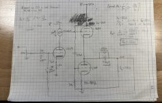
I've been working a bit more on the design - I've settled on using Pete Millett's Cascode CCS board for the input tube.
So far here is the schematic:

Based on this document (https://pearl-hifi.com/06_Lit_Archi...04/Sec_19/991_White_Follower_Optimization.pdf) I tried to optimize the Ra value for the 300ohm load, and found Ra=120Ohm is ideal for a 5687 tube.
Now my question is how do I determine the appropriate B+ voltage for the WCF stage?
I'm also trying to draw the loadline for the WCF and I'm not understanding how to do it. There is some useful information in this thread https://www.diyaudio.com/community/threads/white-cathode-follower-analysis-and-design.299609/ but not enough for me to figure out how to actually draw the loadline.
Any input is greatly appreciated 🙂
So far here is the schematic:
Based on this document (https://pearl-hifi.com/06_Lit_Archi...04/Sec_19/991_White_Follower_Optimization.pdf) I tried to optimize the Ra value for the 300ohm load, and found Ra=120Ohm is ideal for a 5687 tube.
Now my question is how do I determine the appropriate B+ voltage for the WCF stage?
I'm also trying to draw the loadline for the WCF and I'm not understanding how to do it. There is some useful information in this thread https://www.diyaudio.com/community/threads/white-cathode-follower-analysis-and-design.299609/ but not enough for me to figure out how to actually draw the loadline.
Any input is greatly appreciated 🙂
Attachments
- Home
- Amplifiers
- Tubes / Valves
- 12AU7 Driver stage with CCS Load