I’ve almost finished my Tube balanced preamp based on ecc82 and ecc88 in attach, but I could not slove voltage problem. When I connect one of the chaneles to power supply it is working fine, tested sound as well. When I connect both sides/channels to PS voltage started to rise after several seconds and I switched it off. The strange thing is that the heater voltage is also going up.
I have HV Power supply based on 5U4G and with Hammond transformer and choke. I also have one LV Power supply 6.3V for filament of all 4 tubes. Ecc82 supplied with 6.3 parallel. Also when I switch on PS to heaters without HV its also fine, 6.3 stable.
Does anyone experianced the same issue or got an idiea?
Attachments
Last edited:
Code:
... the heater voltage is also going up.I'm new to this, but I recently built an amp. The only direct problem I ran into was that I soldered in the heater wires to the sockets before I did anything else. When I soldered the rest of it, the heater wires were so close to the other pins that it actually melted the insulation of the heater wire, and eventually it shorted a non-heater pin to the heater. The result wasn't immediately obvious except one channel was significantly quieter than the other. After I found it out, I just physically lifted the heater wire out of the way of any pins and the problem went away.
It may not be the same problem, but throwing it out there just in case.
It may not be the same problem, but throwing it out there just in case.
Specifically, heater pin 5 was already soldered, but it's a tight fit with the 12a.7 tubes. When I soldered the plate on pin 6, with the insulation close(but I didn't know it was touching), it melted the heater insulation and came in contact with the plate pin 6.
Last edited:
The heater is using AC, but HV is DC, could the increased voltage is due to DC imposed on AC? If so could have heater to cathode leakage. You can measure any dc resistance between cathode and heater, or use another set of tube. Also monitor the heater voltage without connecting it to 6.3V/12.6V, and determined any increased whether it's DC or AC.Code:... the heater voltage is also going up.
I forgot to mention that heater also supplied by DC. I tried to have it on ground as well as elevated, also I tried with different tubes. But it’s strange, separately it’s working without problem and it sounds great. I agree with you it might be the problem with heater to cathode leakage, but I could not explain why. BTW all 4 tubes Heater are on the same DC PS, 6.3V in parallel.
When I connect both sides/channels to PS voltage started to rise after several seconds and I switched it off. The strange thing is that the heater voltage is also going up.
It almost sounds like the PSU is getting unloaded when you connect both channels, maybe the way you have both channels connected together. Without seeing an exact schematic of how they connect together its imposable to tell.
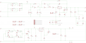
On schematic J4, 1 and 2 both connected to the same hv 260V PS.
Attachments

Last edited:
Just to be sure: Did you try both channels individualy, or just one of the two, and than both together?
Just to be sure: Did you try both channels individualy, or just one of the two, and than both together?
I tested both individually and it works fine, tested sound as well.
I also tested without ECC88 and there wasn’t problem with voltage. When I put both ECC88 voltage going crazy.
How did you arrange for the grounding and elevating of the filament supply? You wrote that you tried both. Did you use a single voltage divider in the HV supply when elevating? And does the grounding also take place there, at only one point? Or does it take place somewhere in the amplifier parts? Perhaps than in one channel its grounded while in the other elevated?
How did you arrange for the grounding and elevating of the filament supply? You wrote that you tried both. Did you use a single voltage divider in the HV supply when elevating? And does the grounding also take place there, at only one point? Or does it take place somewhere in the amplifier parts? Perhaps than in one channel its grounded while in the other elevated?
Single voltage divider in HV. Grinding for HV is one point on PCB. connected to grounding for preamplifier, tag board. LV is elevated to Vhc~40V on the same PCB.
There is one single 260V HV wire connected to preamp part.
Last edited:
From the schematic it shows 126V from J8 directly to pins 4-5 of V1 and no 6.3V but there is a connection from J9 (6.3V) to V2. If there is heater elevation it should come from the center tap of the 6.3V winding. Something looks suspect there.
Never mind I see J8 is 12.6V not 126V the schematic is pretty blurry
Never mind I see J8 is 12.6V not 126V the schematic is pretty blurry
Last edited:
How did you arrange for the grounding and elevating of the filament supply? You wrote that you tried both. Did you use a single voltage divider in the HV supply when elevating? And does the grounding also take place there, at only one point? Or does it take place somewhere in the amplifier parts? Perhaps than in one channel its grounded while in the other elevated?
From the schematic it shows 126V from J8 directly to pins 4-5 of V1 and no 6.3V but there is a connection from J9 (6.3V) to V2. If there is heater elevation it should come from the center tap of the 6.3V winding. Something looks suspect there.
Never mind I see J8 is 12.6V not 126V the schematic is pretty blurry
FYI, Heater is not like it is on schematic, I have one LV 6.3V for all 4 tubes in parallel.
It looks like the amp is oscillating. Can you post the PSU schematic. I don't see bypass caps in the plate supply.
A little bit less than a year ago, you also asked questions about this preamplifier ( https://www.diyaudio.com/forums/tubes-valves/345091-ls60-12au7-balanced-pre-amplifier.html#post5970842).
Did you include a way to control the volume? What is the circuit before J1 and J5? What are you using as a source now? Is it the same source as when you tested the channels individualy? And what is connected at the outputs of your preamp?
Did you measure voltages other than the HV and the filament voltages? Did you adjust VR1 and VR2, and if so, how? Did you re-adjust them when trying both channels at the same time?
Still the big mistery (at least to me) is how the filament voltage could go up. Like koonw in post #2, I tend to think of cathode-heater leaking, but than the amount of leakage has to be pretty high for the filament voltage to up.
How much did the filament voltage and the HV go up?
It looks like the amp is oscillating. Can you post the PSU schematic. I don't see bypass caps in the plate supply.
I’ve done PS based on PCB ordered from hvforless from eBay, very unique and comprehensive. I modified HV part, instead of diode bridge put 5U4G and Hammond choke.
BTW tried with different PS I have already, but as you said preamp oscillating, voltage increasing.., then I switch it off.
Attachments
So despite a regulated B+, the B+ voltage is going up?
And untill now you only mentioned the 5U4G and the Hammond choke for HV.
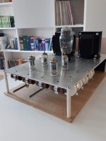
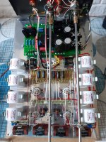
Could you post pictures of your build?
And untill now you only mentioned the 5U4G and the Hammond choke for HV.
Could you post pictures of your build?
A little bit less than a year ago, you also asked questions about this preamplifier ( https://www.diyaudio.com/forums/tubes-valves/345091-ls60-12au7-balanced-pre-amplifier.html#post5970842).
Did you include a way to control the volume? What is the circuit before J1 and J5? What are you using as a source now? Is it the same source as when you tested the channels individualy? And what is connected at the outputs of your preamp?
Did you measure voltages other than the HV and the filament voltages? Did you adjust VR1 and VR2, and if so, how? Did you re-adjust them when trying both channels at the same time?
Still the big mistery (at least to me) is how the filament voltage could go up. Like koonw in post #2, I tend to think of cathode-heater leaking, but than the amount of leakage has to be pretty high for the filament voltage to up.
How much did the filament voltage and the HV go up?
vr1 and vr2 adjusted to 7V each separately. Voltages in all segments going up, it’s like oscillating. E.g. filament voltage 6.3V 6-7 seconds and the. going to 10V, very fast and I switch it off.
Such a beautiful build and than this (for me at least) unexplainable problem.
I can't help with the power supply; my knowledge on SS circuits is poor. I do know that ECC88's oscillate easy (I had to fight that in a crossover with them) but that's not very helpfull for you.
I hope and trust you'll figure it out in the end.
I can't help with the power supply; my knowledge on SS circuits is poor. I do know that ECC88's oscillate easy (I had to fight that in a crossover with them) but that's not very helpfull for you.
I hope and trust you'll figure it out in the end.
- Home
- Amplifiers
- Tubes / Valves
- 12au7 balance preamp voltage problem