Most TDA1543 designs will use 8-9V supply and a I/V resistor between 2-3k to get high output with passive conversion.
But in the datasheet is is stated that the ac part of the output should be kept below 25mV...
My idea is to use a low value I/V resistor (below 10-47 Ohm?) to keep the ac voltage on dac output relative low, and then use a 12AT7 in commen cathode to amplify the voltage up to a useable level (1 V rms)
I have a +B supply in the range of 200-300V for this...and I think ac coupling from dac to grid will be needed.
Any recommendations? Will there be better tubes for the job? I have 4 good RCA 12AT7 on hand...
Will a fully passive solution be better?
How about Rref resistor, when using low I/V ressitors?
Also, using this low I/V resistor, will dac supply in 8-9V range be waste of time?
🙂
Last edited:
Perhaps nobody has tried TDA1543 within specifications? I mean besides using an op-amp in virtuel ground.....
Attachments

Almost all passive I/V circuits for TDA1543 severely violate the data sheet spec for AC voltage output, so are likely to generate distortion. Many circuits also induce peak clipping which the users don't seem to notice. Someone adjusting by ear alone might miss the peak clipping. Adjusting with a spectrum analyser alone might result in two errors cancelling out at one particular signal level only, so you get both peak clipping and more general non-linearity.
My understanding is set out here.
My understanding is set out here.
Hey, you said:
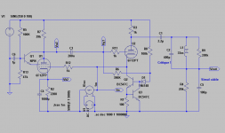
"My eventual aim, once I understand things a little better, is to replace the passive I/V with an active load - probably a grounded-grid triode."
The circuit I've shown above is basically a GG triode (U2) and the current flowing in its plate load resistor is the image of the one flowing in the DAC, plus an offest sunk by the CCS in its cathode.
1543 bias pin was left open.
Since Zin wasn't lo enough, the remaining voltage is amplified/inverted by the pentode (U1) and fed to the grid of the triode introducing near 100% NFB.
(Thanks to F.Blohbaum for the "best penthode" idea)
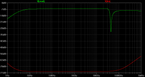
Measurement confirms simulation showing a residual voltage of 200µV at the output of the DAC.
Roughly a 0,1 ohm Zin 🙂
Note that this remains true well above 20Khz while a simple IC OPA (5632) does better . . . only below 300Hz 😱
Yves.
"My eventual aim, once I understand things a little better, is to replace the passive I/V with an active load - probably a grounded-grid triode."
The circuit I've shown above is basically a GG triode (U2) and the current flowing in its plate load resistor is the image of the one flowing in the DAC, plus an offest sunk by the CCS in its cathode.
1543 bias pin was left open.
Since Zin wasn't lo enough, the remaining voltage is amplified/inverted by the pentode (U1) and fed to the grid of the triode introducing near 100% NFB.
(Thanks to F.Blohbaum for the "best penthode" idea)
Measurement confirms simulation showing a residual voltage of 200µV at the output of the DAC.
Roughly a 0,1 ohm Zin 🙂
Note that this remains true well above 20Khz while a simple IC OPA (5632) does better . . . only below 300Hz 😱
Yves.
Interesting idea, although as it is essentially positive feedback will stability be a problem in real life?
Yeap !
Carefull layout and stoppers are a must if you don't want some parasitcs at few hundred kilohertz 😎
I hesitate btwn stating "positive current feed back" or "negative voltage feed back" 😕
The pentode may also be seen as a plate follower amplifier with 100% negative voltage feed back applied to its grid by a vy low impedance source: the triode being seen as a CF . . .
OTH, the positive feed back injected at the grid of the triode artificially sky rocket its Gm.
I do prefer this way of lookin at 😉
Working on this circuit is totally counter intuitive . . . at least for me !
Since it exhibits a "virtual ground" input behaviour, it was perhaps already be used in some tubed mixers as "bus summing amp" ?
Almost all passive I/V circuits for TDA1543 severely violate the data sheet spec for AC voltage output, so are likely to generate distortion. Many circuits also induce peak clipping which the users don't seem to notice. Someone adjusting by ear alone might miss the peak clipping. Adjusting with a spectrum analyser alone might result in two errors cancelling out at one particular signal level only, so you get both peak clipping and more general non-linearity.
My understanding is set out here.
Thank you for the most serious description I have come across on this DAC!
🙂
I have my TDA1543 feeding a resistor voltage divider for the I/V converter.
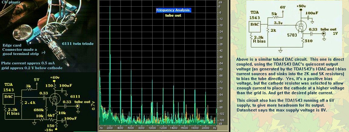
I modified my old Magnavox CDB600 (really a Philips machine) CD player. It uses a TDA1543 "twin DAC" DAC chip, and it used to feed op-amp I/V converter circuits. But I found that this DAC chip seems quite happy to feed a resistive load for the I/V circuit. This DAC chip has, for each channel, a constant source current generator "Ibias" (connected to Vcc 5V), and a varying (to the music) sink current generator "Idac" (connected to ground). The other ends of these current sources join together to create the left or right outputs. The difference current between these two goes into/from the resistor load. It wants a bias of about 2.2V for this resistor load.
This 2.2V bias needs to source or sink current. A conventional voltage regulator chip would only source current but not sink current, so that won't work. But an easy way to create this is to use a voltage divider network, 3k resistor from +5V, 2.4K to ground, to create a thevanin equivalent of a 1.3k resistor going to 2.2V. Of course this +5V needs to be very clean. The DAC develops something like 1Vp-p of audio, which feeds a cathode follower triode grid.
You could just use a resistor to ground if you set Ibias to a value higher than Idac peaks at. I wanted to maintain the average voltage bias the TDA1543 saw with the op-amp circuit, so operating it into a resistor equivalent into a voltage similar to Vref seemed a sensible thing to do. Looked at a resistor going only to ground. But you must set your Ibias to be larger than the max the Idac ever sinks. And the current Ibias - Idac goes into your resistor. As long as Ibias is high enough to keep Idac operating correctly (voltage higher than something like 0.6V?) that should work. A concern I had was that the Idac circuit might not work quite right if the output voltage got too close to ground. The clipping I experienced before I did my above circuit must have been do to insufficient Ibias on Idac peaks. My use of the 2.2V equivalent source avoids that. It allows Idac to exceed Ibias.
I modified my old Magnavox CDB600 (really a Philips machine) CD player. It uses a TDA1543 "twin DAC" DAC chip, and it used to feed op-amp I/V converter circuits. But I found that this DAC chip seems quite happy to feed a resistive load for the I/V circuit. This DAC chip has, for each channel, a constant source current generator "Ibias" (connected to Vcc 5V), and a varying (to the music) sink current generator "Idac" (connected to ground). The other ends of these current sources join together to create the left or right outputs. The difference current between these two goes into/from the resistor load. It wants a bias of about 2.2V for this resistor load.
An externally hosted image should be here but it was not working when we last tested it.
This 2.2V bias needs to source or sink current. A conventional voltage regulator chip would only source current but not sink current, so that won't work. But an easy way to create this is to use a voltage divider network, 3k resistor from +5V, 2.4K to ground, to create a thevanin equivalent of a 1.3k resistor going to 2.2V. Of course this +5V needs to be very clean. The DAC develops something like 1Vp-p of audio, which feeds a cathode follower triode grid.
You could just use a resistor to ground if you set Ibias to a value higher than Idac peaks at. I wanted to maintain the average voltage bias the TDA1543 saw with the op-amp circuit, so operating it into a resistor equivalent into a voltage similar to Vref seemed a sensible thing to do. Looked at a resistor going only to ground. But you must set your Ibias to be larger than the max the Idac ever sinks. And the current Ibias - Idac goes into your resistor. As long as Ibias is high enough to keep Idac operating correctly (voltage higher than something like 0.6V?) that should work. A concern I had was that the Idac circuit might not work quite right if the output voltage got too close to ground. The clipping I experienced before I did my above circuit must have been do to insufficient Ibias on Idac peaks. My use of the 2.2V equivalent source avoids that. It allows Idac to exceed Ibias.
Last edited:
Yes, something like that is the way to do it yet it is surprisingly rare. I suspect that few people have actually read or tried to understand the data sheet. The snag with using valves here is that it is quite easy for the valve to add more distortion than the DAC chip.
Yvesm's circuit in post #4 is very similar to a circuit proposed for implimenting an "anti-triode" circuit some while back. (Used for emulating a SE triode, but using a P-P stage and OT) We needed a very high gm device on one side of a differential pair, sitting on a CCS tail (the real triode went on the other diffl. pair side, instead of the DAC here. the triode and "anti-triode" outputs then drove a P-P xfmr). I don't think anyone ever built it though, we wimped out for a grounded gate Mosfet instead. Maybe time to try it out. Avoids the SS Mosfet in the SE amplifier "purity" stigma.
Don
Don
Yves, I built a SE amp based on these ideas:
http://www.diyaudio.com/forums/tube...chade-pp-anti-triode-ecl86-3.html#post1930300
This is a penthode SE amp with Schade-network feedback; the anti-triode is Large n-channel power FET 2SK2698.
This was built to try to make an SE power amp with toroidal mains trafos.
There are things I would fine tune today, but it works, and it is very happy with cheap TV valves!
"Could you tell more or show a drawing ? ?"
Some description at least here (post #5):
http://www.diyaudio.com/forums/tubes-valves/151220-spud-schade-pp-anti-triode-ecl86.html
I recall posting a diagram once too. May have been the earlier thread by Michael Koster. I'll look for it. There have been at least five threads on the anti-triode idea.
Heh, here is the perfect pentode scheme too (post #11, item #2):
http://www.diyaudio.com/forums/tube...chade-pp-anti-triode-ecl86-2.html#post1918779
That screen current fix idea has been around for some time actually. I saw it somewhere earlier.
Last edited:
Almost all passive I/V circuits for TDA1543 severely violate the data sheet spec for AC voltage output, so are likely to generate distortion. Many circuits also induce peak clipping which the users don't seem to notice. Someone adjusting by ear alone might miss the peak clipping. Adjusting with a spectrum analyser alone might result in two errors cancelling out at one particular signal level only, so you get both peak clipping and more general non-linearity.
My understanding is set out here.
In your sheet you indicate Rref values a factor 1 to 1.5 lower than Rout, if using Rout=27Ohm, should Rref be in that range also?
No, it is not a matter of a simple ratio. Rout=27R is not possible for the usual passive I/V (resistors to ground). The plots on my website show that.
If Rout is attached to an elevated voltage, rather than ground, then Rref might not be needed at all (i.e. Rref=infinity). Or it could be used to set the bias current equal to half the full signal current. This depends on what the DAC is driving.
If Rout is attached to an elevated voltage, rather than ground, then Rref might not be needed at all (i.e. Rref=infinity). Or it could be used to set the bias current equal to half the full signal current. This depends on what the DAC is driving.
Ok, then my circuit idea might not work with 1543. I would use 27R to ground and go AC-coupled from there to high-gain amplifier stage (RIAA like)....
Main purpuse to keep AC-voltage on DAC out below or close to 25mV datasheet limit
But as it is now, with 8.5V Vcc, and 1kOhm for all 3 DAC resistors (pure passive), the sound is very good, in fact impressive....
Might just leave it here?
Main purpuse to keep AC-voltage on DAC out below or close to 25mV datasheet limit
But as it is now, with 8.5V Vcc, and 1kOhm for all 3 DAC resistors (pure passive), the sound is very good, in fact impressive....
Might just leave it here?
- Status
- Not open for further replies.
- Home
- Amplifiers
- Tubes / Valves
- 12AT7 and TDA1543...