Why fixed bias?
Assuming a cap input filter, you'll get a little over 400V with UF4007 diodes and a full wave rectifier. A 5U4 will drop to about 350V (pretty good for a cathode biased 2A3).
With a choke input filter and solid state rectification, your B+ will drop to around 275V.
Assuming a cap input filter, you'll get a little over 400V with UF4007 diodes and a full wave rectifier. A 5U4 will drop to about 350V (pretty good for a cathode biased 2A3).
With a choke input filter and solid state rectification, your B+ will drop to around 275V.
Thank yo ufor quick respons. So with about 270 Volts and 50mA I should still be comfortably within spec' for both voltage and power dissipasjon.
Why fixed Bias - I am thinking about an all-tube design inspired by the Tubelab SE: Schematic | Tubelab
My idea is for a high gain input tube and replacing the FET with a cathode follower. Once I have my chassis built I will start a separate tread on that
Why fixed Bias - I am thinking about an all-tube design inspired by the Tubelab SE: Schematic | Tubelab
My idea is for a high gain input tube and replacing the FET with a cathode follower. Once I have my chassis built I will start a separate tread on that
That is meant to be a flexible design that can be tweaked for various tubes. If you only want to use one, then the ability to adjust plate current isn't so helpful.
What fascinates me with that design is the direct coupling of between driver and output tube. That pluss the use of a high gain input tube without having to worry about drive capability. Current will be fixed at 50-55 mA (OPT spec'ed at <60 mA)
A 5842 will do just fine driving a 45 without any help in between. Do note that the driver tube and output tube are not directly coupled in the design you linked me to.
Thanks everyone,
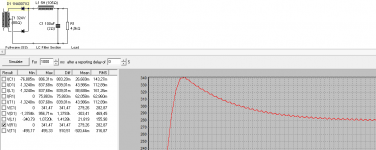
I had all but forgotten about the full wave choke input until reminded otherwise by Audiowize. My head all focused on bridge rectifiers and voltage increasing by a factor of 1.41. Since being reminded I have found links to the PSUD2 here on the forum, downloaded and run some tests.
I am not quite able to simulate my intended configuration, but I believe I should be quite close.
From parts I have at hand for my intended build I was thinking to have one choke and one capacitor per channel, each channel drawing a total of approximately 60mA once I have included the driver stage(s).
attached datasheet downloaded from Hammond webpage and my simulation for one channel.
Any clearing errors in my sim?
What are your recommended diodes for this setup? I was thinking UF4007 unless I am advised otherwise. I have a boxful of 100u capasitors available so no problems increasing capacitor by paralleling. What ripple is acceptable for a single ended 2A3 and is there an optimum capacitor value for my chokes?
Thanks in advance
Lars
Attachments
The problem starts with the fact that the core of Hammond 278CX is hardly (apparently not) capable of delivering over 450 watt secondary power (the slightly larger European standard EI120 is good for 466 watt secondary power with the best quality iron (M6 - 0.35 mm).
For EI120 in the thickest version the core excitation is some 1.7 T with 466 watt secondary power capability; this is about the limit before risk of core saturation.
So, when (but I doubt it) the Hammond has 0.35 mm M6 iron, the core excitation is most likely the main cause of hum. Pulling less secondary power does not help as the problem is already at the primary side.
Yes... That is all point
I have very good experience with custom specified 1T primary in local transformer workshop.
No vibs, no hum, no heat without load, very low Io unloaded.
.
(But I am almost positive that all branded power transformers specified for 60deg C temperture, and 1.2 up to 1.6 Tesla of primary inductance...)
Hi LJT
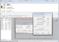
You need to simulate under Load. And you need to use the little source impedance calculator on the mains transformer... Also, if the 100uF capacitors are recent production and reasonable quality, their DCR will be much lower than 2 ohms.
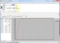
Full wave rectification with silicon using your choke input under constant 120mA load should yield around 265-270VDC. Check my example.
Best regards
Ian
p.s. You will want to by-pass the reservoir caps with at least 100k ohm resistor (2W or higher) to prevent shock hazard when the power is off.
You need to simulate under Load. And you need to use the little source impedance calculator on the mains transformer... Also, if the 100uF capacitors are recent production and reasonable quality, their DCR will be much lower than 2 ohms.
Full wave rectification with silicon using your choke input under constant 120mA load should yield around 265-270VDC. Check my example.
Best regards
Ian
p.s. You will want to by-pass the reservoir caps with at least 100k ohm resistor (2W or higher) to prevent shock hazard when the power is off.
Attachments
Last edited:
Also, don't forget that with silicon rectification, you get immediate full-on B+ voltage. However your 2a3 heaters will not yet be warm enough to conduct. It is not unreasonable to think 10 seconds for the 2a3 to start to fully conduct after heater turn-on.
This means that right at turn-on your circuit draws only a few mA's and the B+ will spike to a value much higher than in the above simulation. Somewhere around 350-400V is what you can expect it to spike to when using silicon rectification. This is not so good for many components, including your 2a3's...
I personally use television damper diodes to rectify since they start up slowly. They do result in an overall lower B+ than silicon, so I sourced my mains transformer accordingly.
Ian
Last edited:
ugh... in post #50 I said "reservoir cap" but in fact they are filter caps.
Anyhow, you will probably see that your intended B+ is less than you might have expected. So what to do?
Well, your mains transformer has a 5v 3A winding, so you could use the venerable GZ34 (5AR4) as a full wave rectifier. You will need to use a small cap on input to get the B+ up, but you could use a higher quality film in this position too. I like DC link capacitors, but motor-run capacitors are also highly regarded.
The GZ34 does not have quite as slow a start-up like TV damper diodes, but it will be much slower than silicon diodes.
Ian
Attachments
- Status
- Not open for further replies.
- Home
- Amplifiers
- Tubes / Valves
- 120mA traffo sufficient for 2A3?