Not to worry, its hard to explain things in the written word sometimes. Thats why these diagrams are awesome. I've hooked up the input as shown, but im getting a lot more static and distortion. It might just be all of the lead wires im using. This stereo jack seems to be defective, so I had to clip directly to the plug. I have a mono jack too, if I use that will it just play one channel? Is the outside of the plug supposed to touch the metal chasis?
If I understand you, soldering to the first (stereo) plug might have melted the insulation and shorted things inside. Not a good plan, as the PVC sleeving insulation is already soft.
If you substitute a mono plug, you will obviously short ring and shaft connections in the socket together when you insert it in your player. So, assuming it doesn't wreck your player, it will simply lose that channel which normally connects to the ring. Don't try it!.
Sorry, you will need to buy or borrow a stereo plug with separate tip, ring and shaft connections if you want this to work as a mono blend or a normal stereo connection. I would simply cannibalise a lead from old headphones and avoid making the awkward connections to those plugs but don't solder to the outside - as explained it will melt the insulation. 🙁
You may be talking about the amplifier end of the lead however, so you can use a mono plug there if your channels are already combined with resistors. I'm sure that's pretty obvious, though.
MP3 players are floating with no connection other than the plug to the amplifier so It can be in contact with the chassis, if that is also signal earth. If it is not connected already to signal earth, then keep the input socket insulated as in most amplifiers.
Last edited:
I haven't soldered anything yet. Ive been using alligator clips. I bought this jacks from futurlec.com and am questioning their quality. I preformed a continuity test and one of the lugs isnt connected to anything on the cable. I am considering just sacrificing the 3.5 mm patch cable like you suggested. I dont want to distroy another MP3 player, so I'll stay away from the mono plug. Haha
Futurlec - well that explains some of the difficulties you have. I know that if you are careful, you can buy fair quality goods from them but they focus on cheapest price first and that's what you get. I don't argue with that regarding semis and other branded quality items but 1-2 months delivery time finishes them for me.
I've had some good luck with Futurlec, although they almost always mess up at least one item in my order. I usually buy hardware such as connectors and resistors from them. All of the transistors in this amp are from them. They seem to have some old stock, as the MJ15003/4 are from Motorola,and they no longer make these. I've check them out and they seem to be legit, not counterfeits.
Needless to say, i don't think I'll be buying anymore audio connectors from them. Its just that the price is so tempting as all the American sites will charge more than double plus taxes, tarifs and force me to pay UPS Fedex 'administrative' fees.
Needless to say, i don't think I'll be buying anymore audio connectors from them. Its just that the price is so tempting as all the American sites will charge more than double plus taxes, tarifs and force me to pay UPS Fedex 'administrative' fees.
theres quite a few digital players out there that need a load on the output to work correctly.
try something like 50ohms across the L & R outputs to ground, and see if it makes a difference in sound.
try something like 50ohms across the L & R outputs to ground, and see if it makes a difference in sound.
I went out and purchased a stereo jack, I've hooked it up with the 10 K resistors, and it sounds better. I've tried to put the 50 ohm resistor across the outputs and can hear no difference. I think part of the problem was that I was using my home brew speaker. The crossover points are a little off and so is the attenuation of the tweeter. It sounds really bright, and it might be out of phase.
At any rate, I have one more question and then I think I can rap this up. I've connected the signal common directly to the ground of the transformer, should I also connect the speakers negative out here as well? Right now I have it connected to the common on the PCB.
At any rate, I have one more question and then I think I can rap this up. I've connected the signal common directly to the ground of the transformer, should I also connect the speakers negative out here as well? Right now I have it connected to the common on the PCB.
Swap those grounds.??
The speaker negative/return/ground needs go directly to the power supply capacitors common ground as close as possible. this point should be near the transformer center tap/common return, but must be near caps.
folks here will tell you they can hear 10mm position difference in this return point!
Input ground should be near to the input transistors on the pcb, but this position is not very critical. usually signal ground and power ground are kept separate, only connected at one point, often with 10ohm resistor.
black art of grounding is the most fun you can have with a working amp! so as above post maybe leave it alone !!
Best of luck anyway.
What's with all the resistors? haha I already have to turn the volume on the source to 3/4. The book doesn't say anything about a resistor. What is the power that would go accross this resistor? I will have to play around with an expendable speaker, the way I have it setup now if the signal common wire comes loose the full rail voltage would go through the speaker. Thanks for the tip, this is all part of the beautiful process.
The 50R resistors are a load for the MP3 player closer to what they are expected to drive with earbuds or headphones. Some believe you have to do this to get optimum sound. They could be right but when I stick a lead in my player it sounds awful with any headphones or anything, so running it into a very tiny load is unlikely to be detectably worse. Just use it as is.
As you use better equipment on your MP3 player, you may notice the shortcomings of MP3 reproduction more. Young folk who have grown up with it don't seem so fussy but others don't rate it as good audio so don't be too concerned about sound quality - it may not be there to have.
As you use better equipment on your MP3 player, you may notice the shortcomings of MP3 reproduction more. Young folk who have grown up with it don't seem so fussy but others don't rate it as good audio so don't be too concerned about sound quality - it may not be there to have.
I also have a tube amplifier with a turntable as a source, with 3 way speakers made of dayton drivers. This amp will be more of a "ghetto blaster'" That I will use for my home gym. However I don't want the sound quality to be too offensive to my ears.
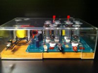
I've attached a picture of my tube amp. This was technically my first amp, but I see it as cheating because I bought a kit with a ready PCB and soldered all of the parts. It was still a lot of work building this enclosure.
It is a 16 Watt Stereo amplifier.
It is a 16 Watt Stereo amplifier.
Attachments
It looks like my project may be a paper weight. I hooked up the amp to a raw power supply. Everything seemed to be fine, however I went to adjust the trim pot as per the instruction in the book; the transformer buzzed and the main fuse blew.
Ever since then it will just blow fuses when I hook it up. I've also used my current limiting supply and it is behaving as if it were being shorted.
I've looked for shorts and can't find any, I dont know what to look for or if this is worth fixing.
Ever since then it will just blow fuses when I hook it up. I've also used my current limiting supply and it is behaving as if it were being shorted.
I've looked for shorts and can't find any, I dont know what to look for or if this is worth fixing.
Oops! I assume that was the trim pot that sets the bias current, and you accidentally set the current way too high. If you can't get it down again with the trimmer, then one or more of the output devices is probably dead. Nothing that can't be fixed, though...
Is there a test that i can do on the transistors when they're still in the circuit? Do I have to unsolder them from the circuit. According to the schematic which are most likely to have died? Thank you for your advice, do you think anything other than output transistors may have gone?
Uh-oh!
Ok Mikedrz, just what differences are there between the first power supply that was working and this new one?
1) Did you double check your polarities are right and you have a voltage that's within what the amplifier is rated to handle without modification?
2) Are you connecting to the same points on the amplifier board as before?
3) Have you fitted supply fuses to protect against this kind of tragedy? (It happens to all of us at some time, I think)
4) Read Godfrey's post again and think about it.
If there is no obvious error powering it up, There must have been either damage or an error in the first instance, so check your board for the correct orientation and polarities of Semis and Electrolytics.
Reconnect the original power supply and verify that it still works or not.
Fit a light bulb (safely insulated please!) in series with the active lead to the mains supply to your power supply, assuming it is a basic mains powered one. and carry out further tests (such as when you repair it) to protect your amplifier. This is to stop it from just becoming toast every time until you discover the mistake. Power up your amp with this and using a low-wattage bulb like 50W until you are satisfied it's working properly an the bulb doesn't glow when the amp is idle..
A simple test for the transistors, which is not complete, is to check the base to emitter voltage of each powered transistor. It should be one diode drop or 0.65V approx. If not, you have toast. You need to read about this stuff and how things work as picking up snippets here and there is no way to learn anything comprehensively so that you can do things for yourself.
You might also take a close look at where that bias pot was set when you touched it. Could it have been set at max. and not min. bias. as caution dictates? 😱
Last edited:
This power supply uses the same two transformers as the current limiting power supply. I've check the polarities before hooking up the amp. The book stated I should see 47mv between the emitters of the output transistors. I have a 2 amp fuse on the primary side of the transformer, as well as the 2 3 amp fuses that are a part of the circuit.
Should I have started with the trim pot at max resistance, or is this oposite? I was only seeing .5 mV during the test which is why I went to the extreme of the pots range.
Can I use my current limiting power supply instead of the light bulb? I will limit the current to under 1.5 amps. When I hook it up as it is now, the supply ics get very hot and the heatsink get very toasty.
Last edited:
I am sorry if I am starting to test everybody's patience. haha However I need to be clear if the max resistance of the trim pot is equal with the 'min' setting of the current bias.
I know how to test a transistor when it is out of the circuit, however I don't know if the same test works while it is in the circuit.
I know how to test a transistor when it is out of the circuit, however I don't know if the same test works while it is in the circuit.
- Status
- Not open for further replies.
- Home
- Amplifiers
- Solid State
- 12 Watt amp, guidance required