I exclusively use 1kV IXYS depletion FETs instead of DN2540 (as upper FET is cascode CCS).
I lost several DN2540 even at 300V (spikes?), so using IXTP FETs is accepted.
TME has in stock IXTP08N100.
IXTP08N100D2 IXYS - Transistor: N-MOSFET | unipolar; 1kV; 0.8A; 60W; TO220-3 | TME - Electronic components
I lost several DN2540 even at 300V (spikes?), so using IXTP FETs is accepted.
TME has in stock IXTP08N100.
IXTP08N100D2 IXYS - Transistor: N-MOSFET | unipolar; 1kV; 0.8A; 60W; TO220-3 | TME - Electronic components
Hi,
I just ordered 10 pcs IXTP08N100D2 IXYS. I will make a test setup first.
I have a Xantrex lab power supply good for 600 VDC @ 2A, so enough to do some serious testing.
Thanks for suggesting this alternative.
Do you use the “standard” diagram or something different?
Regards, Gerit
I just ordered 10 pcs IXTP08N100D2 IXYS. I will make a test setup first.
I have a Xantrex lab power supply good for 600 VDC @ 2A, so enough to do some serious testing.
Thanks for suggesting this alternative.
Do you use the “standard” diagram or something different?
Regards, Gerit
Hi,
I’ve not tried the DN2540 yet, as they are out of stock everywhere. I just checked again today and all stocks are down to zero. Only Ebay/Aliexpress sales, and I have seen too many fraud with imitation components. That is a no go area for me.
So far all my 10M90S have survived my testing (not all 10M45s though).
Regards, Gerrit
I have a few left that I havent put on ebay yet, though I just sold all my listed DN2540.
I didn't realise they were completely out of stock, perhaps
i should've charged more!
I understand that many people say they have bought fakes on eBay.
Luckily I have not had a single bad experience yet, including the j176 I bought for a bargain, that I was alsmot sure would be fakes. However, in testing they appear to be 100% genuine.
there are some reputable sellers of semis on ebay, and whilst I don't sell much, or make any money I only sell from authorised distributors - so I'm reputable, but habent much of a reputation! Small fish in a huge ocean!
Last edited:
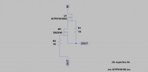
I use only the "standard" (bias resistor between the Zout and Out).Do you use the “standard” diagram or something different?
At 100R the current is about 10mA.
Attachments
Last edited:
Euro21,
OT perhaps, but why use a 1000V part for the cascode top and a another HV part below?
(I have had no issue with a cascode of DN2540, only a single device has proven troublesome, at times)
Typically I will use a HV dMOSFET for the top device and FET as the bottom (or HV BJT at top and low noise BJT at the bottom)
Thanks Euro21, that makes perfect sense!
I prefer to only use cascode anode loads too. I haven't got around to a cathode sink yet.
I also have a lot of the N3 to92, and have done exactly the same
where my original intent was to use lnd150 instead.
But I also like a nice BJT cascode
I prefer to only use cascode anode loads too. I haven't got around to a cathode sink yet.
I also have a lot of the N3 to92, and have done exactly the same
where my original intent was to use lnd150 instead.
But I also like a nice BJT cascode
Last edited:
I use various JFETs as "lower" device (with 1kV depletion MOSFET) in "gyrator".
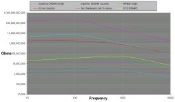
In the cascode CCS the DN2540 is satisfactory, the bandwidth even with high output impedance tubes (as my favorites: 10Y or 801) is reaches 80-100kHz (-3dB).
In the cascode CCS the DN2540 is satisfactory, the bandwidth even with high output impedance tubes (as my favorites: 10Y or 801) is reaches 80-100kHz (-3dB).
How about using a single IXTP08N100D2 for cathode CCS? Has this ever been measured?
Regards, Gerrit
Regards, Gerrit
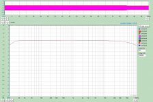
This is my 801a PSE amplifier grid frequency resolution curve (at 1W output).
CCS loaded 841, capacitor coupled to 10Y cathode follower (direct coupled to grids), which has CCS as cathode load (from -200V).
All CCS built with IXTP01N100, DN2540.
Using CCS in cathode is easier (lower impedance), than as anode load, so single device usable.
CCS loaded 841, capacitor coupled to 10Y cathode follower (direct coupled to grids), which has CCS as cathode load (from -200V).
All CCS built with IXTP01N100, DN2540.
Using CCS in cathode is easier (lower impedance), than as anode load, so single device usable.
Attachments
Last edited:
gerrittube,
Did you use any wirewound resistors in the IXYS and 6SN7 circuits?
Not a good idea, if they were.
Did you use any wirewound resistors in the IXYS and 6SN7 circuits?
Not a good idea, if they were.
How about using a single IXTP08N100D2 for cathode CCS? Has this ever been measured?
Regards, Gerrit
If you are good with SMD, you can use BSS159, BSS139 or even 2SK3557, CPH3910 for the lower mosfet-jfet and BSP149 or similar for the upper one. I have been using them in my CCSs for years.
There is a thread regarding oscillation in CCS in the KANDK-forum on audioasylum. Kevin recommends adding a small cap between two of the pins on his CCS boards (DN2540?).
RE: Help with CCS ? - KevinC - K&K Audio / Lundahl Transformers
RE: Help with CCS ? - KevinC - K&K Audio / Lundahl Transformers
Last edited:
- Home
- Amplifiers
- Tubes / Valves
- 10M90S oscillating