My first attempt using the 10M45S as a CCS.
The driver is the pentode section of a 6GH8A running at 3.5mA using LED cathode bias with a 100R resistor to ground and gNFB applied at the junction of the two.
The circuit works fine with a resistor in the anode instead of the CCS. When I switch in the CCS in place of the anode resistor I'm getting some sort of an extreme low frequency feedback or something on the output of the amp.
Before I ran a source through the amp, I had dummy loads connected to the output. I checked the voltages and current with the CCS in place and all measured normal. Correct voltage drop, correct current. I am using a 1K stopper on the gate as suggested by tubelab.
Has anyone had this problem or know where I should start looking?
Thanks,
Scott
motorboating? check your psu decoupling caps, earthing lay-outs....a scheme we can look at will help....
FWIW, mosfets are better used at currents of more than 10mA, cascode bjt's are better at currents less than 10mA.....this is what i gathered from postings here although i have yet to try it myself....
FWIW, mosfets are better used at currents of more than 10mA, cascode bjt's are better at currents less than 10mA.....this is what i gathered from postings here although i have yet to try it myself....
Thanks Tony.
Not sure I would call it motorboating. It's more a very loud low frequency howl. The circuit does work fine with a resistor in the anode instead of the CCS.
I'll come up with a schematic eventually, as most of it is on scratch paper.
Scott
Not sure I would call it motorboating. It's more a very loud low frequency howl. The circuit does work fine with a resistor in the anode instead of the CCS.
I'll come up with a schematic eventually, as most of it is on scratch paper.
Scott
Can't load a pentode with a CCS. Pentodes are also CCS's, and the one will fight the other, causing the oscillation you experienced. If you're gonna do that, you need to parallel a CCS with a plate resistor.
Well thanks Miles. That would explain it. Does this also hold true if the pentode is wired as a triode? The pentode has a 510R resistor from the plate to the screen.
If I wanted to parallel a CCS with the plate resistor, how do I determine the current sharing between the two devices? Is this method discussed somewhere?
Thanks,
Scott
If I wanted to parallel a CCS with the plate resistor, how do I determine the current sharing between the two devices? Is this method discussed somewhere?
Thanks,
Scott
If triode-strapped, it should work fine. I've tried it with a lot of different tubes.
The 10M45 data sheet indicates that it will work down to 2mA. I think I will try a higher current and see what happens.
Thanks.
The 10M45 data sheet indicates that it will work down to 2mA. I think I will try a higher current and see what happens.
Thanks.
I've only used it down to 8mA myself, so I don't know how it works at lower currents. Hence my recommendation to try a higher current.
Correct voltage drop, correct current. I am using a 1K stopper on the gate as suggested by tubelab.
Try 100 ohms.
Try 100 ohms.
I will try that, thanks. My 'current set' resistor is also a 1K. Maybe that's what the problem is.
Your CCS resistor works like in a Jfet CCS, its there to restrict your depletion Mosfet's IDSS to the level you require. The gate stopper creates a low pass though with the gate's capacitance which can be turning the phase at odds with the rest of the system.
So by decreasing the value of the gate stopper I would raise the cutoff frequency to possibly compensate for the effect I am getting?
Not sure what the gate capacitance is for this device.
Thank you,
Scott
Not sure what the gate capacitance is for this device.
Thank you,
Scott
Your CCS resistor works like in a Jfet CCS, its there to restrict your depletion Mosfet's IDSS to the level you require. The gate stopper creates a low pass though with the gate's capacitance which can be turning the phase at odds with the rest of the system.
Its just something you got to try and exclude as a possibility among others. 10M45 needs good damping usually so make sure that your 100 Ohm one will have a very short end to its gate. In many layouts you can't go that low, it sets off self oscillating. Maybe its just your pentode reacting to a CCS on plate. Pentodes are current sources almost due to high internal impedance.
I changed the gate stoppers to 100R.
Pretty much the same. I do realize now that it is only coming from the left channel. The oscillation frequency is 68 or 69 Hz.
I suppose I'll swap the left and right 10M45 boards and see.
Pretty much the same. I do realize now that it is only coming from the left channel. The oscillation frequency is 68 or 69 Hz.
I suppose I'll swap the left and right 10M45 boards and see.
What happens if the cathode bias LED is bypassed with an electrolytic? Or when the LED becomes a resistor?
Keep the gate resistor 1k and replace the cathode resistor that sets the current with a 2k variable resistor and very carefully adjust it in the circuit. If that doesn't make it work then switch to a gyrator (just an extra couple of resistors and one capacitor) which will probably work better anyway. 🙂 (Be careful adjusting that resistor with the high voltage present.)
Is the 6GH8A now triode connected and still not working with CCS?
Yes, that is correct.
What happens if the cathode bias LED is bypassed with an electrolytic? Or when the LED becomes a resistor?
I will try that if needed. I've been kind of busy at work today. Not able to do much.
I'm beginning to think that it may be one of the devices themselves. I can pan over to the right channel before applying the input signal, and if I do that the right channel works fine with the CCS. As soon as a signal hits the left channel though, the 68 Hz oscillation starts. Only in the left channel.
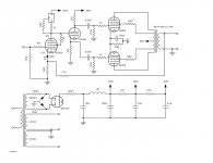
I am attaching a quick schematic of what I've got. The power supply may seem confusing. I'm using a toroid with two 300V secondaries and two 6.3V secondaries. I'm using a separate 300V sec. with 6BY5GA, choke and caps for each channel. The drawing only shows one channel.
I'm using 12.6V for the 10GK6s with a dropping resistor on each filament. I'm powering one 6BY5GA and one 6GH8A with each of the 6.3V secondaries.
Attachments
- Status
- Not open for further replies.
- Home
- Amplifiers
- Tubes / Valves
- 10M45S problem