mach1 said:You would do a lot better using two 10M45S in a casocde arrangement (lowers the shunt capacitance) and taking the output from the top of the current set resistor.
The attachment shows DN2540 depletion mode FETs used in this manner. However the circuit is equally applicable to the 10M45S(an enhancement mode FET with an error amplifier which mimics a depletion mode FET). This arrangement works beautifuly and has a very low output impedance.
Hey Mach1,
Love to see the rest of that schematic if you wouldn't mind sharing. I would have emailed you offline but your not setup for such.
Josh
Snoopyma
I have a hard time putting how something sounds into words, but is guess the
MU-Follower sounded warmer….
Which might be the same as saying less Solid State like?
It also seems to me that I have less HUM, but I can’t prove that. I measure .6mV at the
Speakers with the CD on pause. That’s the same as with the 10M45, however it seems to be less noise at the speakers than before.
One thing I will say, The MU-Follower sounds way, way better than SRPP.
To me, the SPRR sounded like my speakers where in a cave…
Keep in mind this is just my personal preference…
It all comes down to what sounds best for You
Konnichiwa,
Yes, it will work fine, but it will actually work very well with an even simpler cicrcuit. Been there, done that, works actually better than an all tube Mu-Follower and omits that coupling capacitor into the bargain.
And don't worry about the all the complainers and cascoders and the like. Safe to surmise they are wrong. In most application cascoding makes very appreciable little difference with the 10M45 (it does with a lot of other devices though).
Sayonara
sgerus said:In general… think this will work?
Yes, it will work fine, but it will actually work very well with an even simpler cicrcuit. Been there, done that, works actually better than an all tube Mu-Follower and omits that coupling capacitor into the bargain.
And don't worry about the all the complainers and cascoders and the like. Safe to surmise they are wrong. In most application cascoding makes very appreciable little difference with the 10M45 (it does with a lot of other devices though).
Sayonara
Attachments
Josh,
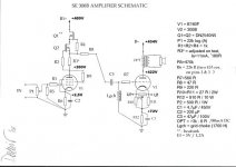
I have attached the full schematic, as you requested. It came from the audioroundtable website and was drafted by Damir. The long thread on the design of this amp is well worth reading.
If you are going to use a 10M45 ccs I would encourage you to try both the single chip and cascode versions and see which you yourself prefer. In Mr Reed's immortal words 'just remember different people have peculiar tastes'. They are very affordable and the circuitry is very simple.
good luck !
Attachments
Thanks Mach,
I am just trying to figure out how much gain this circuit will provide. According to my Siemens data sheet, for the C3g triode connected, mu is 40. I know that with CCS loading, mu is maximized, or does the mu follower CCS provide additional gain?
Josh
I am just trying to figure out how much gain this circuit will provide. According to my Siemens data sheet, for the C3g triode connected, mu is 40. I know that with CCS loading, mu is maximized, or does the mu follower CCS provide additional gain?
Josh
Josh,
A ccs will always cause a horizontal load line, giving you the full mu of the tube. A really easy way of determining mu at any chosen operating point is to draw both a horizontal and vertical line through the operating point on the plate curves. Move one volt along the horizontal line (ie one volt change in cathode voltage), project another vertical line down to the x-axis, then read off the corresponding change in plate voltage between the two points. The change in plate voltage = mu.
This method is equally applicable to resistive load lines, and can be used to determine the mu of any tube (both triode and pentode) at any operating point. All you need is the plate curves.
mach1 said:You would do a lot better using two 10M45S in a casocde arrangement (lowers the shunt capacitance) and taking the output from the top of the current set resistor.
The attachment shows DN2540 depletion mode FETs used in this manner. However the circuit is equally applicable to the 10M45S(an enhancement mode FET with an error amplifier which mimics a depletion mode FET). This arrangement works beautifuly and has a very low output impedance.
Hi Machi,
Would you mind sharing how to implement the use of 2 10M45s in a cascode arrangement? I am a layman here so I don't know how to apply the cascode of the DN2540s to the 10M45s. Thanks.
Regards,
T.C. MA
Thanks Mach,
I haven't gotten back recently because I was down with a nasty bug. Feelin better now... I was reading up in my newly acquire Morgan Jones book.
I guess I am trying to confirm that I am figuring this out correctly. The gain as I calculate it with the above schematic and using the C3G (w/ ccs) will be ~8x.
C3g mu x 300B mu / N (tx turns ratio) =
40 x 3.5 / 17.32 ~= 8
Is this correct?
Josh
From the turns ratio 17.32:1 I assume you are using a 2400:8 ohm transformer. With a low load like that the 300B mu will drop to around 2.9 (using STC plate curves), giving you a theoretical gain of approx 6.7.
pm
From the turns ratio 17.32:1 I assume you are using a 2400:8 ohm transformer. With a low load like that the 300B mu will drop to around 2.9 (using STC plate curves), giving you a theoretical gain of approx 6.7.
pm
Re: Re: 10M45 Mu-Stage Idea?
Hi KYW, thanks for that. One question, why the 6 ma bleed on the output of the 10M45? Is that to bring it up to min specified operating current? And is to meet the recommendations of the spec sheet or have you found it makes a worthwhile (measureable/audible) difference?
Kuei Yang Wang said:.......In most application cascoding makes very appreciable little difference with the 10M45 (it does with a lot of other devices though).
Sayonara
Hi KYW, thanks for that. One question, why the 6 ma bleed on the output of the 10M45? Is that to bring it up to min specified operating current? And is to meet the recommendations of the spec sheet or have you found it makes a worthwhile (measureable/audible) difference?
Re: Re: 10M45 Mu-Stage Idea?
What happens if the resistor between the 10M45s and the plate of tube is replaced with a plate choke of 25H inductance and 340 ohm DCR? Will there be any benenfits?
Thanks.
Regards,
T.C. MA
Kuei Yang Wang said:Konnichiwa,
Yes, it will work fine, but it will actually work very well with an even simpler cicrcuit. Been there, done that, works actually better than an all tube Mu-Follower and omits that coupling capacitor into the bargain.
And don't worry about the all the complainers and cascoders and the like. Safe to surmise they are wrong. In most application cascoding makes very appreciable little difference with the 10M45 (it does with a lot of other devices though).
Sayonara
What happens if the resistor between the 10M45s and the plate of tube is replaced with a plate choke of 25H inductance and 340 ohm DCR? Will there be any benenfits?
Thanks.
Regards,
T.C. MA
Re: Re: Re: 10M45 Mu-Stage Idea?
Konnichiwa,
Not my idea. The original poster wanted it, it makes sense though for the ECC83 frontend, as it would draw very little current.
Sayonara
Konnichiwa,
rdf said:One question, why the 6 ma bleed on the output of the 10M45?
Not my idea. The original poster wanted it, it makes sense though for the ECC83 frontend, as it would draw very little current.
Sayonara
Re: Re: Re: 10M45 Mu-Stage Idea?
Konnichiwa,
The "virtual"resistance of the CCS will increase, how much depends on many factors. I'd probably leave the choke out, myself.
Sayonara
Konnichiwa,
snoopyma said:What happens if the resistor between the 10M45s and the plate of tube is replaced with a plate choke of 25H inductance and 340 ohm DCR? Will there be any benenfits?
The "virtual"resistance of the CCS will increase, how much depends on many factors. I'd probably leave the choke out, myself.
Sayonara
Several people have asked why the bleeder resistor…..
I was just following the example from the “Mu-Stage” article as mentioned in the initial post. I think it makes sense to have the chip operate at around 5-10 mA and bleed of the excess, rather that trying to operate the chip at the low end of it’s operating range.
In the process of testing this I was able to get the 10M45S to work as low as 1.1mA
-I stopped testing at that point; note that the spec sheet says the chip is rated down to 2mA.
Actual test data:
1650R = 1.83mA
2K = 1.6 mA
3K = 1.1 mA
You will drop at least 4 volts across the chip.
Also tested this chip as a “B-follower”… basically a SRPP with the chip replacing the resistor that was between the top and bottom valve.
It worked, but it sounded terrible. I don’t remember the details... gave up on that test right away.
(see Morgan Jones Valve Amplifiers, 3rd edition, p125)
I have put this idea on hold for now… just wanted to share that I learned in the process.
Thanks sgerus. I benched both versions last night for a short time with a 958 acorn. Into a 100k load the lowest distortion version by far was taking the output directly from the 10M45s 'K' terminal without the bleeder, the CCS running at 3.34 ma. Swinging ~20 volts p-p the second harmonic was -66 dB below fundamental. Taking the output from the plate directly it jumped 6 dB. The bleeder required to bias the cicuit at 10 ma was in the 13 kohm range and caused the distortion to rise dramatically. I didn't listen to any of them.
A quick question
what's the min voltage drop (input-output) the IXYS needs to see to work properly, if any?
I am thiking to a low voltage application.
Thanks
Gianluca
what's the min voltage drop (input-output) the IXYS needs to see to work properly, if any?
I am thiking to a low voltage application.
Thanks
Gianluca
- Status
- Not open for further replies.
- Home
- Amplifiers
- Tubes / Valves
- 10M45 Mu-Stage Idea?