Hi,
I found this input stage: Muchedumbre XL at Muchedumbre XL – wauwatosa tube factory
I have built it and it works quite well, but unfortunately with insufficient output for my purpose. With 0.71 VRMS in I get 0.66 VRMS out, so the amplification is just below unity. As often with Google's results the amplification, input / output impedances, etc. were not clearly mentioned in this article.
I need a driver stage with 6 to 10 dB amplification, with a 6SN7 dual triode (and using both triodes).
What could be the best way to get this result?
Regards, Gerrit
Attachments
I've seen a few Broskie articles over at tubecad around that configuration too. He's also added hybrid SS to output more power. If you google "cathode follow tubecad" or "white cathode follower" and look at the images, the majority of them are tubecad articles.
If the next stage is high input impedance you could do a mosfet cascode (folded if you want) through with the 6SN7 then providing a cathode follower driver that would give you drive power that the cascode would find difficult.
Or retrograde with a BJT: Retrograde Cascode if you don't mind some solid state.
I think you have lots of options. Just need to know more how it's connecting in (ie impedances etc).
Last edited:
Gerrit,
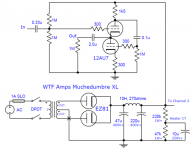
The article you quoted describes that circuit as a buffer so one would expect it to have a gain slightly less than unity. If you are looking for something simple, the attached circuit would probably work. It has a gain of about 10 dB (x3.2). It is a common cathode gain stage with cathode degeneration to control the gain, direct coupled to a cathode follower.
As NickKUK says, you have a lot of options. But this circuit has a high input impedance and a low output impedance so it should be suitable for most applications. One note: it is overall inverting, in case that matters to you.
Attachments
Hi NickKuk,
I’ve read a lot about Broskie’s designs, but it’s hard to find out about the specifications for each design. I want to use minimal sand, but I would like to know more about your MOSFET cascode.
For now I use a MOSFET as phase splitter (works very well so far). So the impedance of that stage will be quite high. This splitter has approx. unity gain.
Regards, Gerrit
A cascode typically results in a high gain, it also has the added bonus of low miller effect and therefore offers a good bandwidth. The downside is that it output is high impedance - hence the use of drivers. To give an idea - I can get a 1-4V input as 1 to 100Vpp output of a pair of 17mu 12bh7a in cascode. More than enough - the same would be possible with the 6SN7 (also mu 17 IIRC).
You could use a single tube in a couple of of ways:
1. In-> Input 6sn7 -> cascote 6sn7 -> mosfet driver.
2. In-> Input 6sn7 -> cascade mosfet -> 6sn7 as a driver
There's a few differences between the mosfet types used: cascode 👎 and folded cascode (p).
Rob Coleman sells a board IIRC that provides a solid state 'folded' cascode to add to the input tube. The benefit of using a folded cascode is the reduced voltage range required. Example of how it would fit in: DHT Folded Cascode Experiments – Bartola(R) Valves
6SN7 likes it's HT voltage so stacking two 6SN7s increases the voltage required.
Designing a cascode is a little more complex than a single tube stage but Merlin's pages has a step by step approach to calculating the required resistances, load lines etc: The Valve Wizard
Thinking about it - if you have a mosfet phase splitter and use a base input - that's basically a high impedance input so you could simply try using the 6SN7 -> 6SN7 -> into the mosfet as an option. The cascode by itself (no driver) may have enough power to overcome the gate capacitance of the splitter.
Steph @ skunkiedesigns has a couple of threads and YouTube series on making the 6SN7 cascodes: Boyuurange / Reisong A50 300B Tube Amp Advanced Mods Part One - YouTube
I have to say I'm not as familiar with the 6SN7 as I am the 12BH7A which I have cascoded. However I would say that Broskie's designs are more conceptual, with the addition of things such as PSRR given the cascode has lower PSRR which make seeing the cascode in it's easiest form.
Last edited:
If you build a properly designed 6SN7 Cascode, the output impedance can effectively be the top plate load resistor, RL, because the top plate rp is high.
By properly selecting a plate load resistance, RL, you can get the gain to be low to moderate, and the output impedance to be low to moderate.
You can use self bias with a bypass cap (or other classic and new bias methods, fixed, LEDs, etc.)
The circuit can have low distortion. And it can be very simple, and low parts count.
The limit of all that is not the gain and output impedance, the limit of all that is the maximum voltage swing.
6dB = gain of 2; 10dB = gain of 3.16 (root of 10).
Go for it!
"You should make things as simple as possible, but no simpler." - Albert Einstein
Last edited:
- Home
- Amplifiers
- Tubes / Valves
- 10dB line driver stage