I have to agree with darkfenriz
And say that I have seen 100-reds of better amplifiers.
Some points:
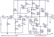
A) Q5 and Q7 is the same(NPN). So called Quasi complementary.
There is no need to make such a solution today.
We have good True complementary NPN+PNP pairs.
B) D1, D2, R9 and R10. They form a bias control for output stage.
There is no reason not to use a proper Transistor for this.
C) C4, R11 and R12. A so called Bootstrap.
Bootstrapping is an old technique.
This was probably because of lack complmentary VAS transistors.
Better to use a proper current source. 2 transistors + 2 resistors.
D) The input pair Q1, Q2 get their current from R3, R4.
Just like in the Bootstrap case, we should use a proper current source to feed Q1.Q2.
This will improve performance with several levels!
It is not that amplifier will not work.
It is that the quality of the work it can perform is bad.
If we compare with even a basic amplifier like the Blameless.
Here is the Blameless.
You can find those details I mention.
You have to mirror it upside down to compare
We can find more reading at Douglas Self amplifier Institute
The Amplifier Institute.
And say that I have seen 100-reds of better amplifiers.
Some points:
A) Q5 and Q7 is the same(NPN). So called Quasi complementary.
There is no need to make such a solution today.
We have good True complementary NPN+PNP pairs.
B) D1, D2, R9 and R10. They form a bias control for output stage.
There is no reason not to use a proper Transistor for this.
C) C4, R11 and R12. A so called Bootstrap.
Bootstrapping is an old technique.
This was probably because of lack complmentary VAS transistors.
Better to use a proper current source. 2 transistors + 2 resistors.
D) The input pair Q1, Q2 get their current from R3, R4.
Just like in the Bootstrap case, we should use a proper current source to feed Q1.Q2.
This will improve performance with several levels!
It is not that amplifier will not work.
It is that the quality of the work it can perform is bad.
If we compare with even a basic amplifier like the Blameless.
Here is the Blameless.
You can find those details I mention.
You have to mirror it upside down to compare
An externally hosted image should be here but it was not working when we last tested it.
We can find more reading at Douglas Self amplifier Institute
The Amplifier Institute.
If other circuits are too complex for you, this is also a good choice:

Its based on the harman kardon citation 12 and modified by nelson pass to use mosfets in the output stage.
Its based on the harman kardon citation 12 and modified by nelson pass to use mosfets in the output stage.
hello.
to me it looks like a cheap old style schematic.
c1,c3 are too tiny ,they cut off the bass...........c5 is very big........bias control is primitive...........and so on.
there are better schematics ,simple and cheap,like p3(a) or so........
greetings
to me it looks like a cheap old style schematic.
c1,c3 are too tiny ,they cut off the bass...........c5 is very big........bias control is primitive...........and so on.
there are better schematics ,simple and cheap,like p3(a) or so........
greetings
If other circuits are too complex for you, this is also a good choice:
Its based on the harman kardon citation 12 and modified by nelson pass to use mosfets in the output stage.
3904s and 3906s ? Better not be running more than +/- 20 Volts - and that's at the red line. 40 Volts would give 25 Watts into 8 ohms. Seems a wee bit shy of 100 Watts or is it for 2 ohm loads? The current rating of the output devices is high but won't there be problems with adequate gate drive to Q6?
G²
If other circuits are too complex for you, this is also a good choice:
Its based on the harman kardon citation 12 and modified by nelson pass to use mosfets in the output stage.
About the Nelson Citation 12 MOSFET.
I have great confidence in Nelson Pass. It probably works.
But I would not do that way. Probably not even Nelson today!
The weak spot is the VAS in my opinion.
The current in VAS is: Vsupply/(4.7k+4.7k)
For 30 Volt we get ~3 mA in VAS.
For 20 Volt we get ~2 mA in VAS.
If I was to drive big MOSFET (HEXFET), I certainly would use more current than 2-3 mA.
Not below 10 mA, for me.
Which means I would use other transistor than 2N3904 for Q3.
To hot up the gain we could even consider a 2 transistor darlington for VAS.
But I think this is not necessary.
It all boils downto how much global gain and feedback you want.
And how much total harmonic distortion (THD) you think you can tolerate.
I have lots of faith in Nelson Pass but you missed the point. Gain doesn't mean squat when the transistor fails because you're trying to use a 40 Volt transistor in a 70 Volt system. It lets the smoke out.
G²
None of the small signal transistors actually have 70v between C and E.
Im running 2x35V just fine, no prollems at all. I'll leave it up to you to believe that or not.
Im running 2x35V just fine, no prollems at all. I'll leave it up to you to believe that or not.
Why bother with low Vceo devices at all ?? I use the same 120V devices for LTP and 300v VAS trannies in my 40v amps as in my 80v amps. They don't cost any more , so why not eliminate the problem totally ??? 😕
This is DIY , why not have a voltage stage that can run from 30v rails to 100v rails ??
OS
This is DIY , why not have a voltage stage that can run from 30v rails to 100v rails ??
OS
In my case, i took what i had on hand, also i had to use transistors with a hfe as close to the originals as possible, only 2N3904/6 did that out of the transistors i had at hand.
In my case, i took what i had on hand, also i had to use transistors with a hfe as close to the originals as possible, only 2N3904/6 did that out of the transistors i had at hand.
Things have gotten cheap. I get 25 ea. of Ksa992/Ksc1845 for $4USD , any grade. lowest grade (P) will be direct 200hfe replacement for any 2n-XXXX.
OS
None of the small signal transistors actually have 70v between C and E.
Im running 2x35V just fine, no prollems at all. I'll leave it up to you to believe that or not.
Q3 and Q5 most certainly will as soon as you drive some high levels. If they haven't failed yet you're just plain lucky because it's _always_ a bad idea to exceed maximum ratings.
http://www.onsemi.com/pub_link/Collateral/2N3903-D.PDF
G²
I've driven the amp into hard clipping, even had the input voltage up to 10V by mistake with no ill effects.
Anyways if i build another one i consider using 2N5551 and 2N5401 which are 150V rated NPN and PNP and cheap enough, i checked hfe and it seem to be within spec.
Anyways we have driven this thread offtopic enough now, see my thread in the pass section if you wanna continue this "chat" about it.
If you want simplicity, two LM3875/3886 in parallel will make some 100+ W into 4 ohms and some 50-60W into 8 ohms, and its so simple that you don't even need a board, just remember to use two 100mohm resistors to parallel the outputs.

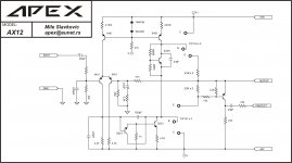
Apex, Could you provide a larger version of the schematic ?
It does look similar to the old elektor amp using TIP142/147 darlingtons except that dident have current sources.
It does look similar to the old elektor amp using TIP142/147 darlingtons except that dident have current sources.
Apex, Could you provide a larger version of the schematic ?
It does look similar to the old elektor amp using TIP142/147 darlingtons except that dident have current sources.
Use full screen, picture is in high-resolution. Amp was based on 'Carvin' B100 amp.
Regards
Even the fullscreen image is a bit small, the component values are barely readable.
AX12 schematic
Attachments
- Status
- Not open for further replies.
- Home
- Amplifiers
- Solid State
- 100watt amplifier