hi all,
why ax 20 which I have made the volume more slowly than the ax14, if this is so the character of ax 20 (ax 14 TEF)?
thanks
why ax 20 which I have made the volume more slowly than the ax14, if this is so the character of ax 20 (ax 14 TEF)?
thanks
Mr. Mile,
This gonna be my next project to follow, please let me know if you found an error.
Thanks...
Regards,
Does the pcb right?
sr200 & ax20 what one is better than other?
sorry for bad eng
Last edited:
Does the pcb right?
sr200 & ax20 what one is better than other?
sorry for bad eng
This is AX-20 extended with 5 pair, but "NOT TESTED" yet.
I will update and confirm soon once pcb is tested.
Regards,
Thanks for your effortsThis is AX-20 extended with 5 pair, but "NOT TESTED" yet.
I will update and confirm soon once pcb is tested.
Regards,
In your opinion, which of sr200 & ax20 is better?
Thanks for your efforts
In your opinion, which of sr200 & ax20 is better?
I haven't build SR 200 yet, i suggest you to ask Mr. Mile, he is the right one who can answer all your questions about this 2 amp.
Last edited:
Finally figured out the problem...one of the resistors was miss valued by quite a bit.
I fixed the resistor and took the amp for a spin. Running about 65 mV across 0.22 ohm emitter resistors and the large sinks barely get warm.
I am really going to enjoy this amp...good treble...commanding bass and the amp is very quiet. I still need to clean up a little wiring and post a pic.
The amp boards and psu board are all homemade etch via toner transfer method.
Thank you Apex!
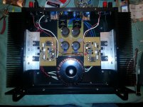
Here is a pic...The speaker protects are not hooked up yet but it did not thump at all upon startup or shutdown.
Nice?! 🙂 It look´s great man! Well done!
Here is a pic...The speaker protects are not hooked up yet but it did not thump at all upon startup or shutdown.
Nice work, and nice picture. I suggest to revert positions of transformer and PSU and you have short wires instead long from AC input to the transformer and from transformer to PSU. Bias transistor (BD139) must be connect on heatsink with outputs.
Regards
Last edited:
Hi, mr. Slavkovich.
Are there any changes to be done with parts if I want to use your PSU-5 design with +-36V AC?
Thanks
Are there any changes to be done with parts if I want to use your PSU-5 design with +-36V AC?
Thanks
Apex hai ...hi all,
why ax 20 which I have made the volume more slowly than the ax14, if this is so the character of ax 20 (ax 14 TEF)?
thanks
what is my post? is there any comment from you? thanks
mr apex.., good advising! i am going to use my stock mj15015s and '016s in Nazirdigi's 4 pairs ax20. as i read the MJ's pdf online i knew its less powerful than what they are using here as powers. i am planning to maximize as possible the supply voltage to its safe extent. what can you advise? thank u vry mch sir.
@Nazirdigi.. congrats for your vry successful 4 pair ax20 and its protect.. can u post here their pcbs for printing? i thank u much in advance..
btw expert friends, i am planning also to make an amplifier for my lead guitar. can this also be excellent? i am going to have this in a single channel and i think a pair of outputs is enough. thanks to u all
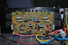
Hi miles, I assembled AX-20 amp I have attached layout. Problem with this layout is, there is no connection between Q9 - Q18 and Q8 - Q17. I easily fixed by using MJE340-50 lead as jumper at copper side. My problem is I am not able to adjust bias, amp is playing music every thing seems right.
Attachments
Last edited:
hi, Sonal Kunal
if you look at the scheme, there will be a dc current that comes out on the speaker output, because there is one diode 'IN 4007' an inverted installation, the voltage of the diode is positive. you try to watch another scheme,
Regards
if you look at the scheme, there will be a dc current that comes out on the speaker output, because there is one diode 'IN 4007' an inverted installation, the voltage of the diode is positive. you try to watch another scheme,
Regards
yes thats in layout but in board I have place correctly, there is only 10-15mV dc at output. I'll post picture soon.
Last edited:
I connected amp in series with 10Ω resistance, when nothing seems to burn I put fuse and tried to adjust bias but was not able to, even winding trim-pot to full. Amp was playing music but with crossover distortion at low volume.
Attachments

- Home
- Amplifiers
- Solid State
- 100W Ultimate Fidelity Amplifier