Next amplifier
Hi at all,
after finishing the Quasi amplifier for beginners i started as new project the AX14. Here the first picture from PCB for the prototype.
First amplifier was confiscated by my son, so i have to build a new one ;-)
regards, Olaf
Hi at all,
after finishing the Quasi amplifier for beginners i started as new project the AX14. Here the first picture from PCB for the prototype.
First amplifier was confiscated by my son, so i have to build a new one ;-)
regards, Olaf
Attachments

AX-20 layout
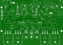
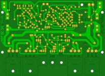
Hey guys here is a layout to show you guys how it looks I'm not done yet, if someone see an error please let me know I would really appreciated, also if some one notice something out of place please tell me I don't mind at all, I'm not perfect, it took me some time but here is,😀
I hope mister Apex like it too.
Regards
vargasmongo3435
Attachments


@vargasmongo3435, that amplifier you're talking about has been built by @44250 himself! Somewhere in between Mr. Aleksandar called it A100, but it seems to be D14 with darlington outputs, what seems to be a previous version of AX-14, the main goal in this thread.
Hope this helps.😎
Sory,that is the one that has a few names (D14/AX100) and i have remembered it by the D14 name. I haven´t built that one but i did similar-AX12/B80. That one (D14/A100) was built by the ElektronicarPG and it has given him abot 171 W at +/-60Vdc supply at 8R non-reactive resistance,without visible distortion od output signal. The supply voltage should be smaller than +/-60Vdc but even than there would be plenty of power at the output.
Sorry for the offtopic...

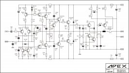
Here is the AX-20 schematic to support......
Regards,
Wiljj78
Thanks man! now I can number the components awesome dude! 😀
Regards
vargasmongo3435
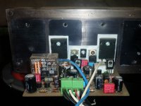
this is my AX14P (with protector), i like the bass so deep and tight
Nice work, is this AX14P, can you share your pcb?
Attachments
Hey guys here is a layout to show you guys how it looks I'm not done yet, if someone see an error please let me know I would really appreciated, also if some one notice something out of place please tell me I don't mind at all, I'm not perfect, it took me some time but here is,😀
I hope mister Apex like it too.
Regards
vargasmongo3435
Nice pcb, I suggest to add protect from AX14P instead LED indicators.
Nice work, is this AX14P, can you share your pcb?
yes i use that schematic, i'll share the PCB later, i've got trouble with my corel draw, can't open the file now
Hi at all,
after finishing the Quasi amplifier for beginners i started as new project the AX14. Here the first picture from PCB for the prototype.
First amplifier was confiscated by my son, so i have to build a new one ;-)
regards, Olaf
Nice pcb, don't forget to connect input gnd to psu gnd.
Regards
I'm confuse to be honest
Hello guys a I have to stop for a moment because I copied this layout and the LED indicator got me really confuse, mister Apex suggest it to use AX14P circuit protection so has some one already build this layout with the LED indicator before? I mark some areas that I'm not sure or in other words confuse 😕 I don't want it to mess it up bad, any help? I'm like this character."😱" lol
Regards
vargasmongo3435
Attachments

![AX-20.LAY]vargasmongo3435.jpg](/community/data/attachments/279/279043-c47e5d9dc756f8140062b898f497ea9f.jpg?hash=xH5dncdW-B)
Last edited:
Nice pcb, I suggest to add protect from AX14P instead LED indicators.
Hello mister Apex!, did some one build it with this LED indicators? that is why I have to stop, I can replace them with the relay protection and is someone want to build it with the LED indicators I can have two layout versions you think is a good idea? 🙂
Regards
vargasmongo3435
Hello mister Apex!, did some one build it with this LED indicators? that is why I have to stop, I can replace them with the relay protection and is someone want to build it with the LED indicators I can have two layout versions you think is a good idea? 🙂
Regards
vargasmongo3435
For LED indicators I suggest this circuit
Apex vu meter - YouTube
Regards
oh I see sir on the video, can you share the layout? I mean if you can. 😀
Regards
vargasmongo3435
Regards
vargasmongo3435
oh I see sir on the video, can you share the layout? I mean if you can. 😀
Regards
vargasmongo3435
check this,
post no- 622,and 626
http://www.diyaudio.com/forums/solid-state/167394-quasi-amplifier-beginners-63.html#post3033841
Hello guys a I have to stop for a moment because I copied this layout and the LED indicator got me really confuse, mister Apex suggest it to use AX14P circuit protection so has some one already build this layout with the LED indicator before? I mark some areas that I'm not sure or in other words confuse 😕 I don't want it to mess it up bad, any help? I'm like this character."😱" lol
Regards
vargasmongo3435
Hello Juan,
Can you share PCB Layout.....
Also please make vertical position on those output tranies i will try to etch your pcb design...
Regards,
Wiljj78
Hello Juan,
Can you share PCB Layout.....
Also please make vertical position on those output tranies i will try to etch your pcb design...
Regards,
Wiljj78
Sure bro hold on
Wiljj78 😀 I send you the files by e-mail, I also send you the Sprint Layout 5 file in case you want it to open it and make any corrections, if you can't just mark it with paint program ans send it to me and I can fixed, really appreciated dude.
Regards
vargasmongo3435
Regards
vargasmongo3435
Attachments

Last edited:
- Home
- Amplifiers
- Solid State
- 100W Ultimate Fidelity Amplifier