It was set at 10mV over the gate resistors 🙂
OK, that would mean around 40mA on each resistor. Fine. I had overbiased it to 59mA.
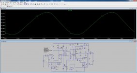
Anyway, I'm getting this glitch on the sinusoid using 1KHz. This is not the first time I see glitches on the LTP out, and it usually gets right after the VAS.
I can send the asc file for you to check if I'm doing something wrong.
Attachments
@apexaudio is the one to talk to about this,
I'm just a hobbyist with basic electronics knowledge,and I don't really look at simulations that much,
I've built this amp and it sounds good and works as it should,and that's what I care about 😀
I'm just a hobbyist with basic electronics knowledge,and I don't really look at simulations that much,
I've built this amp and it sounds good and works as it should,and that's what I care about 😀
And I have no doubts it should sound good, because many people are building Apex amps instead of buying unreliable amp kits on eBay.
My intention is not to criticize Apex's designs, as I find them very elegant and simple, which can be misleading on their sophistication.
I'm doing this research on several amps, old and new.
If I intended to criticize something I would PM Apex, and no put my questions here. He's a generous person who is sharing his knowledge with us, and that's not easy to find in this world.
mosFET output stage do not have the equivalent to BJT optimal ClassAB bias.OK, that would mean around 40mA on each resistor. Fine. I had overbiased it to 59mA.
Anyway, I'm getting this glitch on the sinusoid using 1KHz. This is not the first time I see glitches on the LTP out, and it usually gets right after the VAS.
I can send the asc file for you to check if I'm doing something wrong.
MosFETs start with lots of crossover distortion when bias is very low, reducing to some crossover distortion when bias is high and gets to very low crossover distortion when the bias is getting near ClassA. Only at full ClassA do BJT and FET output stages have zero crossover distortion.
Summary.
BJT - bias to ClassA, or to optimal ClassAB
FET - bias to ClassA, or as hot as the heatsinks will allow in ClassAB.
He's a generous person who is sharing his knowledge with us, and that's not easy to find in this world.

How many tech's are there in the world today ?................ and how many of that FIGURE do actually share their knowledge openly to others willing to learn !
That's exactly what I said and mean.
To come to a forum and get into a brawl for matters of ego, and not just talk out your opinions in a nice conversation, where everybody wins, is plainly foolish.
BTW: the FH12 mod2 runs very well and specs are exactly as said.
THD @ 20KHz was a bit less: 0.0099%. You can increase input level a bit more, like 1.5v, before the amp clips.
The asc sim schematic is a bit different from the pdf one.
Andrew: you're right on how bias affects distortion on this FET amp and others. You just play with the bias and see that.
BTW, I had another look at the pdf file, and it does spec 148w @ 8 ohms. Which is what I got on my sim when I increased the input level.
For those that know LTSpice: how is it possible that output result when the supply is just +/- 60v?
I ask this because I did get similar results with other amps. Is LTSpice showing fake results?
For those that know LTSpice: how is it possible that output result when the supply is just +/- 60v?
I ask this because I did get similar results with other amps. Is LTSpice showing fake results?
It is not a 148W/8 ohm maximum, but THD at 148W/8Ohm.
For mosfet model, please use Bob Cordell model with sub-kthreshold in some where in this forum.
For safety reason, I suggest to use +/- 56V PSU.
For mosfet model, please use Bob Cordell model with sub-kthreshold in some where in this forum.
For safety reason, I suggest to use +/- 56V PSU.
I probably sounded like I'm ignorant,that wasn't my intention,I've built a lot of Mile's designs and I respect him sharing his knowledge with us,I answered like I did because I can't check that simulation(don't know how to do it),and that's why I referred to Mile.
I'm sorry if I offended anyone,wasn't my intention.
I'm sorry if I offended anyone,wasn't my intention.
I probably sounded like I'm ignorant,that wasn't my intention,I've built a lot of Mile's designs and I respect him sharing his knowledge with us,I answered like I did because I can't check that simulation(don't know how to do it),and that's why I referred to Mile.
I'm sorry if I offended anyone,wasn't my intention.
If you did not like opened your mind, it is OK 🙂
I like every thing that bring new idea for me. Although, if it is not their original idea, i don't care. I learned from many member in this forum: Mile (Apex), Hugh Dean (Aksa), Nelson Pass, Dadod, Bonsai, Keantoken, Bob Cordell, Douglas Self, etc.
Sometime, I share my idea, too.
It is not a 148W/8 ohm maximum, but THD at 148W/8Ohm.
For mosfet model, please use Bob Cordell model with sub-kthreshold in some where in this forum.
For safety reason, I suggest to use +/- 56V PSU.
Bimo,
What does it exactly mean "THD at 148w/8ohm"?
If that output is not possible with the actual amp, which should be clipping with that input level and such a supply, how should it be interpreted? A fantasy output?
As I said, this is not the first amp I found that shows such results.
BTW, I had another look at the pdf file, and it does spec 148w @ 8 ohms. Which is what I got on my sim when I increased the input level.
For those that know LTSpice: how is it possible that output result when the supply is just +/- 60v?
I ask this because I did get similar results with other amps. Is LTSpice showing fake results?
a 230:dual 40Vac transformer operating on a UK supply of 240Vac gets a 3pair output stage to ~ 37.3Vac (52.7Vpk or 105.5Vpp)Bimo,
What does it exactly mean "THD at 148w/8ohm"?
If that output is not possible with the actual amp, which should be clipping with that input level and such a supply, how should it be interpreted? A fantasy output?
As I said, this is not the first amp I found that shows such results.
This is equivalent to 174Watts into 8ohms, from a PSU+quiescent amp that idles @ ~ +-58.5Vdc
This same amplifier (Leach Lo Tim) managed 49.9Vpk into 4r0, clip free.
With 60Vdc you should be able to get even higher clip free output.
Last edited:
Hello.Can you post some phono preamp schematics ?There were some schematics posted by APEX using opamps and discrete but i cant find the posts.
Bimo,
What does it exactly mean "THD at 148w/8ohm"?
If that output is not possible with the actual amp, which should be clipping with that input level and such a supply, how should it be interpreted? A fantasy output?
As I said, this is not the first amp I found that shows such results.
In simulation, I use power supply with zero output impedance or in reality it use regulated power supply.
P = V x V / R, P = power, V = Voltage, R = load impedance
148 = V x V/8
V = 34,4 rms
V peak = 34,4 x 1,414 = 48,6V.
Because it is not using bootstrap at VAS then V peak max for PSU 60VDC is about 52V. Then 48,6V is below clipping.
Of course if you use non regulated PSU, clipping voltage must below 52V. Maybe clipping voltage is around 47V because voltage drop on PSU.
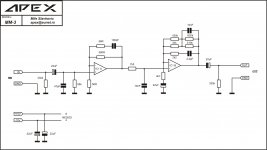
Here you are RIA phono pre by Apex.
Hello.Can you post some phono preamp schematics ?There were some schematics posted by APEX using opamps and discrete but i cant find the posts.
Attachments

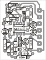
Here you are RIA phono pre by Apex.
thanks .and any other discrete?
thanks .and any other discrete?
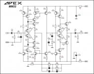
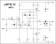
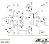
There is MM28, MM22, MM4, MC4, MC10... in this thread
There is MM28, MM22, MM4, MC4, MC10... in this thread
Thank you.I found them all.MM28 and MM22 use many parts.Is there a PCB layout for MC10 and MM4?
Which one do you prefer among all the designs?Which one sounds better?
Attachments
- Home
- Amplifiers
- Solid State
- 100W Ultimate Fidelity Amplifier