link to AA14: 100W Ultimate Fidelity Amplifier
scroll a very short distance down the page to the other one.
mlloyd1
scroll a very short distance down the page to the other one.
mlloyd1
I can't seem to find the AA9 or AA14 amps in the thread - can you provide links?
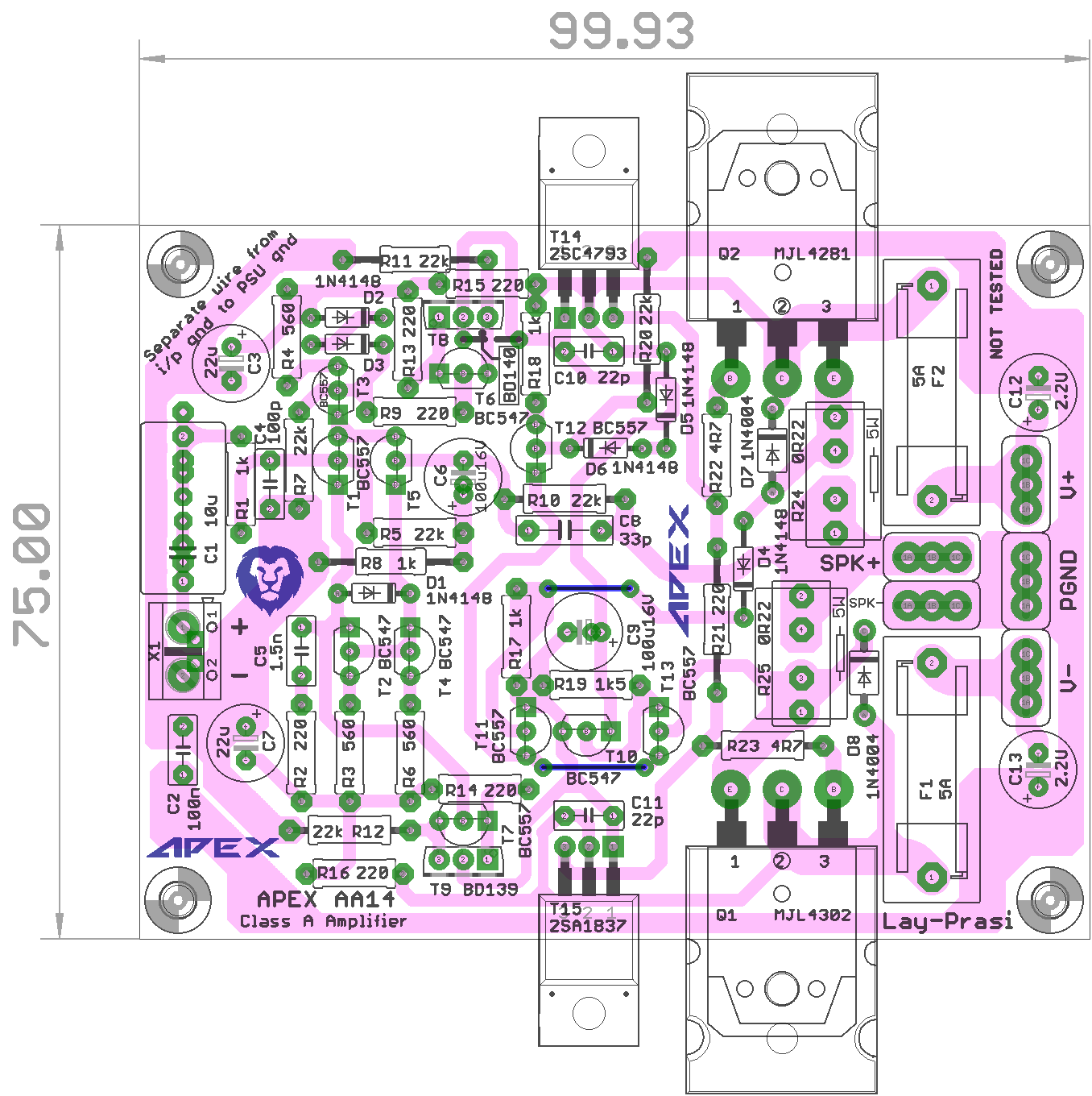
Ahh I remember now. A beautiful layout be Prasi.
I might have to get the 10 for $2 deal at EasyEDA
How many watts is this amp and what is suggested PSU voltag and bias current setting?
I might have to get the 10 for $2 deal at EasyEDA
How many watts is this amp and what is suggested PSU voltag and bias current setting?
Ahh I remember now. A beautiful layout be Prasi.
I might have to get the 10 for $2 deal at EasyEDA
How many watts is this amp and what is suggested PSU voltag and bias current setting?
There is 1300mA auto bias circuit on AA14, can be set with change 0R22 resistors. Use +/-24V PSU for 20W.
Hi, here is a SMD version to the inverted preamp. There is no real reason to make the layout so small, just for fun. It is then also my limit for DIY etching. Maybe someone has fun with it.
Thanks Mile and a little late happy birthday!
regards Olaf
Great DIYer. Thank you very much. I love it.
There is 1300mA auto bias circuit on AA14, can be set with change 0R22 resistors. Use +/-24V PSU for 20W.
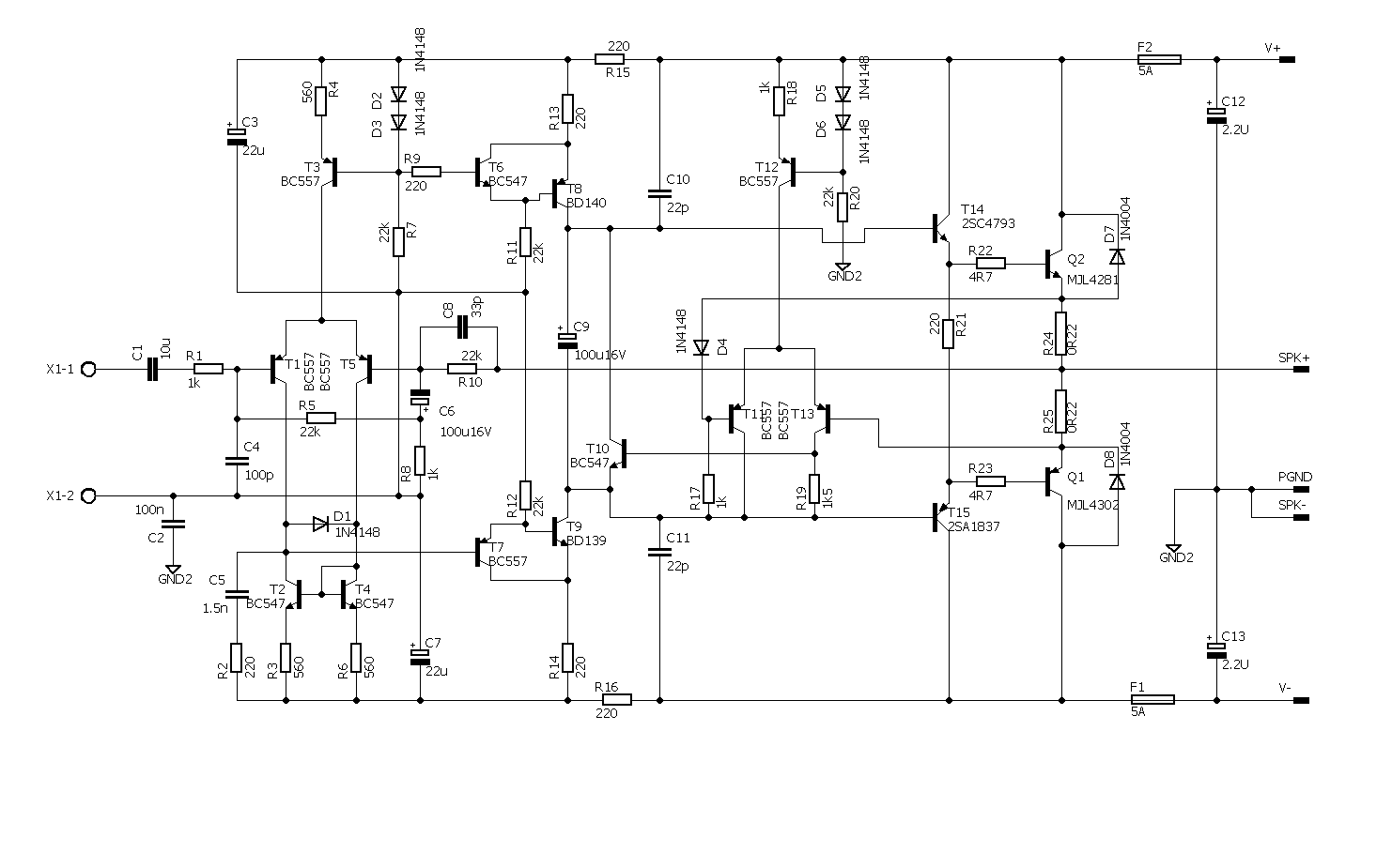
Ok, I see it now - the current is read by the voltage drop across the two 0.22R (0.44R) with a 0.563v delta added by the 1N4148 and then the error is amplified by the LTP which then drives the T10 to control the bias to bases of outputs. Will this prevent thermal runaway reliably? 24v rails is perfect, although 20w is a little less than I would have hoped for.
Very clever auto bias though.
Thermal runaway is posible only with Vbe multiplier bias circuit in class AB amplifier. 25W/8R is maximum expected power with +/-24V rails for any amplifier, use PSU5 regulated PSU.
Ok, I see it now - the current is read by the voltage drop across the two 0.22R (0.44R) with a 0.563v delta added by the 1N4148 and then the error is amplified by the LTP which then drives the T10 to control the bias to bases of outputs. Will this prevent thermal runaway reliably? 24v rails is perfect, although 20w is a little less than I would have hoped for.
Very clever auto bias though.
I read this bias on Douglas Self book. He claim it is better than Nelson Pass bias with single transistor with feedback (like FA9).
Ok I am sold on this design especially with the clever auto bias circuit - so from D Self then? I will order up some boards then as I have a case with 24v supplies.
@Bimo, would you say your FX8 mod with 24v rails in Class A with 1amp bias is also 25w max amp?
@Bimo, would you say your FX8 mod with 24v rails in Class A with 1amp bias is also 25w max amp?
@Bimo, would you say your FX8 mod with 24v rails in Class A with 1amp bias is also 25w max amp?
It become about 20W rms at 8Ohm or 35Wrms at 4Ohm.
But in class A mode will operate until 16W rms at 8 Ohm or 8W rms at 4 Ohm, more than that will become class AB.
Mr mile
Finally i built a23 ampli yesterday
I put kse340-350 instead mje's
I did not find lm4562 in my city and want put lm833 or tl072 instead it.which one ic is better?
Finally i built a23 ampli yesterday
I put kse340-350 instead mje's
I did not find lm4562 in my city and want put lm833 or tl072 instead it.which one ic is better?
Lm833 has less noise and less thd(0.002 vs 0.01)
But tl072 has better slewrate(16 vs 7)
Mr mile plz guide me
But tl072 has better slewrate(16 vs 7)
Mr mile plz guide me
Hello Mister Mile,
A friend (Purrhula) ask me to adjust his A33 amplifier.
The question is what must be adjust with the bias potentiometer.
And how do I do this.
I hope that you can help me.
Regards,
Mans.
A friend (Purrhula) ask me to adjust his A33 amplifier.
The question is what must be adjust with the bias potentiometer.
And how do I do this.
I hope that you can help me.
Regards,
Mans.
mr mile plz answer to my question
i tested my a23 and ampli is work
i have 14 volt dc on pins 4 and 8 ic(7v on zener pins).is this normal?
how i adjust bios in a23?


i tested my a23 and ampli is work
i have 14 volt dc on pins 4 and 8 ic(7v on zener pins).is this normal?
how i adjust bios in a23?
Don't the Sziklai pairs T6/T8 and T7/T9 need to be swapped?
Best regards!
Don't the Sziklai pairs T6/T8 and T7/T9 need to be swapped?
Best regards!
They are not Sziklai pairs.
Sajti
i tried to adjust bias in a23
so i put multimeter probs on point A and B in bottom pic
i adjust BIAS pot and now i have 25mv bias
is this correct?

so i put multimeter probs on point A and B in bottom pic
i adjust BIAS pot and now i have 25mv bias
is this correct?
i tried to adjust bias in a23
so i put multimeter probs on point A and B in bottom pic
i adjust BIAS pot and now i have 25mv bias
is this correct?
View attachment 639784
Yes.
i tried to adjust bias in a23
so i put multimeter probs on point A and B in bottom pic
i adjust BIAS pot and now i have 25mv bias
is this correct?
View attachment 639784
@Bahrad
With your measurements @ testing points TP A-B (your pic),
with emitors resistors 2x0R33 @25mV is quiet good,
this is 35-38mA per output BJT pair
try to biasing @50mV, this is 50mV/0R66=75mA per output BJT pair,
if the main heatsink maintens lower temp then 55°C.
This is the temp that you can touch the heatsink with your fingers
for more then approximately 5sec
or measure precisely with adequate temp-meter. 🙂
You will have less crossover distorsion, better THD...
- Home
- Amplifiers
- Solid State
- 100W Ultimate Fidelity Amplifier