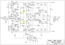
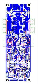
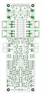
Here are schematics BOM and gerbers of the amp described in https://www.diyaudio.com/community/threads/200w-mosfet-cfa-amp.243481/page-75#post-6000469
Damir
R20 and R24 in the amp are there for overcurrent protection, but used value is a bit to high, better use 1.5k instead 6.8k.
Damir
R20 and R24 in the amp are there for overcurrent protection, but used value is a bit to high, better use 1.5k instead 6.8k.
Attachments
Last edited:

If you follow the above link it will direct you to the main thread with the schematics and all other needed information.
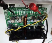
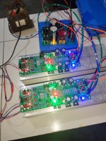
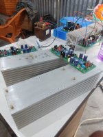
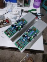
Ok I have time before I'm away, here is a finished 100w CFA. Excellent sound, CFA is growing on me. Supply is unregulated +/-50vdc, bias is around 100mA, VAS current is a bit high at 10mA VAS trs are heating up and current through R5 R6 are around 2mA.
Attachments
You can use 5k there, but strange that you can't find 4k7, it is most common value.
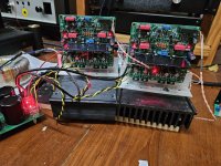
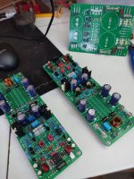
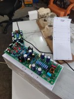
I see that you use different layout, actually I prefer to have output transistor in one line to keep them on the same temperature level.
Also I use N P N P configuration to get lower power supply loops influence.
Could you show your layout?
Damir
I see that you use different layout, actually I prefer to have output transistor in one line to keep them on the same temperature level.
Also I use N P N P configuration to get lower power supply loops influence.
Could you show your layout?
Damir

first, i was immediately impressed with the audio quality.
the guitar sound is classic.
i like your design damir.
thanks for sharing.
the guitar sound is classic.
i like your design damir.
thanks for sharing.
Attachments
- Home
- Amplifiers
- Solid State
- 100W CFA with mosFET OPS