Partiendo de una potencia de +-45 V, me gustaría armar un amplificador de 100 w con un solo par de 2SC5200 y 2SA 1943. ¿Me pueden recomendar un esquema fiable? Adjunto algunos esquemas que he encontrado de los cuales no tengo opiniones. Serían con solo un par de transistores de salida. Gracias.
Attachments
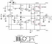
"Starting from a power of +-45 V, I would like to put together a 100 w amplifier with a single pair of 2SC5200 and 2SA 1943. Can you recommend a reliable scheme? I attach some schemes that I have found of which I have no opinions. They would be with only a couple of output transistors. Thank you."
1. A single pair of C5200/A1943 is asking for failure with a ±50V supply.
2. Tip41/42 are too slow for drivers.
3. Separate 100 Ohm resistors to turn off the outputs is too slow and asking for shoot-through current failure. They should be cross-coupled.
4. While VI protection can cause issues, you should at least have current limit protection.
5. A current mirror on the LTP is better for turn-on/off thumps as well as general performance.
6. Especially with a current mirror, the LTP needs to be degenerated to reduce slew distortion.
7. A Darlington VAS improves THD. See Douglas Self's web site.
8. The feedback decoupling cap should be voltage clamped.
...
Attachments
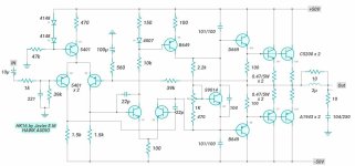
1. A single pair of C5200/A1943 is asking for failure with a ±50V supply.
2. Tip41/42 are too slow for drivers.
3. Separate 100 Ohm resistors to turn off the outputs is too slow and asking for shoot-through current failure. They should be cross-coupled.
4. While VI protection can cause issues, you should at least have current limit protection.
5. A current mirror on the LTP is better for turn-on/off thumps as well as general performance.
6. Especially with a current mirror, the LTP needs to be degenerated to reduce slew distortion.
7. A Darlington VAS improves THD. See Douglas Self's web site.
8. The feedback decoupling cap should be voltage clamped.
...

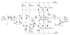
Would this design fit the characteristics you mentioned?"Starting from a power of +-45 V, I would like to put together a 100 w amplifier with a single pair of 2SC5200 and 2SA 1943. Can you recommend a reliable scheme? I attach some schemes that I have found of which I have no opinions. They would be with only a couple of output transistors. Thank you."
Attachments
1. A single pair of C5200/A1943 is asking for failure with a ±50V supply.
2. Tip41/42 are too slow for drivers.
3. Separate 100 Ohm resistors to turn off the outputs is too slow and asking for shoot-through current failure. They should be cross-coupled.
4. While VI protection can cause issues, you should at least have current limit protection.
5. A current mirror on the LTP is better for turn-on/off thumps as well as general performance.
6. Especially with a current mirror, the LTP needs to be degenerated to reduce slew distortion.
7. A Darlington VAS improves THD. See Douglas Self's web site.
8. The feedback decoupling cap should be voltage clamped.
...
Thank you
Attachments
And likely few hundred more versions.Would this design fit the characteristics you mentioned?
Very common topology.
People would change few things here and there.
But for the most part would work.
Or a final design would be similar.
Has VI limiters
which many would leave out.
Depends on application.
Few strange values here and there.
Sure others will post more eventually.

Thank you, I want to use it as the final stage of a combo for electric bass. I will wait for possible corrections or contributions.
The design you are proposing is a EF3 output stage. Is this an existing design with tested PCBs? If not, do you have experience biasing and stabilizing a EF3 output stage? It can be tricky even for experienced designers.
Have you considered the Wolverine? It's a EF3 that have been tested with 2SC5200/2SA1943. In its EF3 3-pair configuration with 49V rails, it's rated for 100W into 8 ohms. This seems to be what you are looking for and is a proven design with excellent support and high performance.
If you really want something you can design yourself, I'd suggest starting with an EF2.
For reasons of space it would have to be EF2. Any EF2 scheme that works with +-45V DC and that is capable of delivering 100w (or slightly less) over an 8 Oh speaker? Thank you
Not sure I understand the space comment. Are you trying to fit this in a certain size chassis? If so, what size?
Chassis size doesn’t have an impact on EF2 or EF3 topologies. This simply indicates if predrivers are used.
Chassis size doesn’t have an impact on EF2 or EF3 topologies. This simply indicates if predrivers are used.
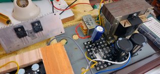
In my design each module already has an assigned space. Power supply, preamplifier and power stage. Since my stage idea was with a single pair of 2SC5200-2SA1943, I installed a radiator with the two final transistors. I no longer have the possibility of placing another radiator, so the best thing would be to put two more transistors on that same radiator. But I already have the power supply so I must take advantage of it. That is why I was asking you specifically about that type of amplifier. Thank you
Attachments

Sorry for my confusion,😱 I mean 2 pairs of output transistors.Not sure I understand the space comment. Are you trying to fit this in a certain size chassis? If so, what size?
Chassis size doesn’t have an impact on EF2 or EF3 topologies. This simply indicates if predrivers are used.
I don't see a path for a ±45V supply and a single pair of 2SC5200-2SA1943 without a risky SOA. I suspect your best option if you want to retain the more expensive items (chassis and PSU), is a design with a pair of lateral mosfets. These should be fine with a ±45V supply.
Mooly's CFP lateral mosfet singleton might fit your needs. It's runs from one pair of lateral MOSFETs on a ±45V supply and is good for around 100W into 8R. It's also a proven design with many existing PCB variants: My MOSFET amplifier designed for music
Mooly's CFP lateral mosfet singleton might fit your needs. It's runs from one pair of lateral MOSFETs on a ±45V supply and is good for around 100W into 8R. It's also a proven design with many existing PCB variants: My MOSFET amplifier designed for music
- Home
- Amplifiers
- Solid State
- 100w amplifier with a single pair of 2SC5200 and 2SA1943