Hi everyone
I am in the process of making a very basic guitar amp around the 100w mark.
I have a large 160w sub woofer speaker driver that I have read will work well as they work in the same frequency as a guitar. (Not sure if that's true)
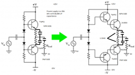
I have an op amp for the pre-amp and plan to run 2n3055 and mj2955 complementary pairs in a push pull configuration for the power amp (current gain stage). Possibly a few pairs of them running in parallel.
I suppose I have a few questions as I am very new to all of this.
Since I can get enough voltage gain (I figure this because as I turn the gain up on the op amp it starts to clip and I figure this is just due to the fact that the transformer I have only puts out 37v in total and that the amplifier is hitting the tops and bottoms of the voltage rails? Or would this be happening internally in the op amp?.
I don't have an oscilloscope.
I don't have alot of money either and want more volume and power so I have a plan to get the transformer from a microwave oven and re-wind the secondary coil with wire that is double the thickness of the primary and wind on half as many turns as the primary to give me a 1 to 2 ratio (half of 240v).
Would this be a cheap good way of getting a high voltage high current power supply providing I can quieten it down with filtering?
Also - if my components can handle it, would it be a really stupid idea to get the primary from another microwave transformer and put it onto the core of the first microwave transformer so I am getting 240v out? If I get transistors, caps and rectifiers that can all handle over 240v will this enable me to get ridiculous amounts of power providing I can get the necessary voltage gain?
Any help and opinions would be appreciated
Regards -
Damien
100V AC will produce 1.414 X 100!
2N3055/MJ2955 die above 115V.
You will need a centre tap so 60-0-60 is still a bit on the high side. How many turns has the microwave oven primary got?
2N3055/MJ2955 die above 115V.
You will need a centre tap so 60-0-60 is still a bit on the high side. How many turns has the microwave oven primary got?
I don't think the sub woofer driver will make a good guitar speaker. It is designed to produce lower frequencies than guitar. Remember, guitars have harmonics that extend well past what a sub woofers are designed for. A typical guitar speaker freq. response spec is 70-5 kHz. I doubt the sub will extend to that upper spec of 5 kHz.
Do you know what the freq. response spec is for your driver?
Do you know what the freq. response spec is for your driver?
Dear Damien, with due respect, from what you write and how you write it I can guess you are quite green at this.
Hi everyone
I am in the process of making a very basic guitar amp around the 100w mark.
I have a large 160w sub woofer speaker driver that I have read will work well as they work in the same frequency as a guitar. (Not sure if that's true)
I have an op amp for the pre-amp and plan to run 2n3055 and mj2955 complementary pairs in a push pull configuration for the power amp (current gain stage). Possibly a few pairs of them running in parallel.
I suppose I have a few questions as I am very new to all of this.
Since I can get enough voltage gain (I figure this because as I turn the gain up on the op amp it starts to clip and I figure this is just due to the fact that the transformer I have only puts out 37v in total and that the amplifier is hitting the tops and bottoms of the voltage rails? Or would this be happening internally in the op amp?.
I don't have an oscilloscope.
I don't have alot of money either and want more volume and power so I have a plan to get the transformer from a microwave oven and re-wind the secondary coil with wire that is double the thickness of the primary and wind on half as many turns as the primary to give me a 1 to 2 ratio (half of 240v).
Would this be a cheap good way of getting a high voltage high current power supply providing I can quieten it down with filtering?
Also - if my components can handle it, would it be a really stupid idea to get the primary from another microwave transformer and put it onto the core of the first microwave transformer so I am getting 240v out? If I get transistors, caps and rectifiers that can all handle over 240v will this enable me to get ridiculous amounts of power providing I can get the necessary voltage gain?
Any help and opinions would be appreciated
Regards -
Damien
Not a sin, we all started at ground level and proceeded to the upper floors.
Short answer, you can't do what you want from what you have, period.
I am happy you are interested in this wonderful hobby, I suggest you read as much as you can, a book will be much better , (because it will present knowledge in a logical way and won't advance to a subject until it explained what you need in an earlier chapter) than reading random pages in the Internet.
You really need to start with basic concepts, and progress step by step .... as with anything else.
If you want to build something, good, get a protoboard and some basic tools (multimeter, soldering iron, pliers, wire cutter, assorted screwdrivers, etc.) and start building a basic project.
An LM386 based amplifier comes to mind, google Smokey amp schematic.
That alone will give you lots of pleasure, because it will work, can be assembled in a protoboard without even soldering (you'll need to solder input and output jacks though) and sounds GOOD .
From there on, the Sky is the limit.
https://www.youtube.com/results?search_query=smokey+amplifier
Thanks for all of your input people it has been fun reading your responses.
JMFahey: What book do you recommend would be good for me?
So far I have built class A amplifier gain stages of common emitter and common collector (Havn't tried common base as these just confused me for some reason)
I have also built a Class AB push pull output stage with tip41c and tip42c complementary pairs so if you can suggest a good book for my skill level I would appreciate that. Yes you're right I'm pretty green at this, only been at it for 6 months or so as a part time hobby but so far really enjoying it! =)
For all reading this -
I do have a working class AB amplifier which will take line level signal and boost it to speaker level but I want more volume.
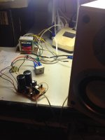
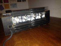
I realized after cranking up the voltage a little (Yep it got louder!) I got more volume from the amp but then my components were under rated in both terms of voltage and current so I decided to do the whole thing again but just make it bigger with 2n3055&MJ2955's instead of tip41c and tip42C (To-220 upgraded to To-3 package) Just incase there is anyone here that are unfamiliar with the transistors I have listed. Used higher voltage caps & bigger resistors and wires and a Huge transformer I found inside a powered sub woofer on the side of the road. I'm not sure what it's current handling capacity is but it's HEAVY! Torrodial type - I'll post a picture of that too.
SO yeah, I put all that together (Yes I realize the to3 transistors require heat sinks so I havn't even powered it up yet)
Before I start just randomly upping the voltage to get more current I thought perhaps all I need is more current gain?
So I'm playing with the idea of using a a complementary darlington pair for my output stage but I'm scared as last time I tried to make a darlington pair on a breadboard one of the transistors just overheated instantly.
I've done the maths & have it written down somewhere but I came to the conclusion that I will need SEVERELY limited base current going to the bases of the tip41c & tip42c's in order to get an acceptable idle current flowing through the collector emitter regions of the to-3 transistors. Am I right?
I'll post a schematic of what I intend to do.
Any input would be appreciated. Thanks in advance!
Regards
Damien Apperley.
JMFahey: What book do you recommend would be good for me?
So far I have built class A amplifier gain stages of common emitter and common collector (Havn't tried common base as these just confused me for some reason)
I have also built a Class AB push pull output stage with tip41c and tip42c complementary pairs so if you can suggest a good book for my skill level I would appreciate that. Yes you're right I'm pretty green at this, only been at it for 6 months or so as a part time hobby but so far really enjoying it! =)
For all reading this -
I do have a working class AB amplifier which will take line level signal and boost it to speaker level but I want more volume.
I realized after cranking up the voltage a little (Yep it got louder!) I got more volume from the amp but then my components were under rated in both terms of voltage and current so I decided to do the whole thing again but just make it bigger with 2n3055&MJ2955's instead of tip41c and tip42C (To-220 upgraded to To-3 package) Just incase there is anyone here that are unfamiliar with the transistors I have listed. Used higher voltage caps & bigger resistors and wires and a Huge transformer I found inside a powered sub woofer on the side of the road. I'm not sure what it's current handling capacity is but it's HEAVY! Torrodial type - I'll post a picture of that too.
SO yeah, I put all that together (Yes I realize the to3 transistors require heat sinks so I havn't even powered it up yet)
Before I start just randomly upping the voltage to get more current I thought perhaps all I need is more current gain?
So I'm playing with the idea of using a a complementary darlington pair for my output stage but I'm scared as last time I tried to make a darlington pair on a breadboard one of the transistors just overheated instantly.
I've done the maths & have it written down somewhere but I came to the conclusion that I will need SEVERELY limited base current going to the bases of the tip41c & tip42c's in order to get an acceptable idle current flowing through the collector emitter regions of the to-3 transistors. Am I right?
I'll post a schematic of what I intend to do.
Any input would be appreciated. Thanks in advance!
Regards
Damien Apperley.
Attachments
If at all possible, I suggest taking "the long path" , which is long (duh!) but very solid.
Don't know what books are current and easy to find at High School libraries in USA, but for the strongest foundations basically:
Start with a high school level *Physics* book 😱, the one which covers Electricity and Magnetism.
Many complain saying "but I want to learn Electronics, more specifically Audio related stuff"
Fine, this is what such a Physics book will teach you (mentioned in no particular order) :
Electron
Voltage
Current
Conductor
Insulator
Resistor
Capacitor
Electric Field
Powerou
Switch
Connexion (connector)
Potentiometer
Battery
Power supply
Transformer
Coil
Magnet
Inductance
Frequency
Generator
etc. etc.etc.
And you will understand the real definition of each thing, not those confusing examples such as "electricity along a wire is like water in a garden hose .... " which explain 1 thing and confuse 10 .
And then you will *quickly* understand a transistor (because you already learnt the "building blocks") explained as "a current controlled variable resistor" , a Tube or Fet explained as "a voltage controlled variable resistor" , a capacitor as "an element made out of 2 parallel conductor plates separated by an insulator" and so on.
I suggest a real old book (even 1920s or so) 😱, which spends more time explaining the concept of what each thing is, and is very light on Math, using Algebraic Math as we use here : addition/substraction/division/squares/roots/etc. and not Calculus which is fine for the most obscure aspects but not really needed for everyday use.
Then some similar lever "Introduction to Electronics" course.
I repeat, can't suggest specific names because I'm in another Country, which uses another Language, , but a visit to a Library will suggest a couple.
In fact, if you find someone you like, please post at least name and author here ( a download link even better if available) and let me check it.
The main thing is that you want to learn the right way 🙂
No probs JM
If you think that I am lacking fundamental knowledge I will go back and revise and I'll let you know if I come across any good books, everything I have learnt so far has been from web pages, forums, you-tube and experimentation.
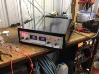
I've completed a couple of projects - Duel DC variable power supply & the picture of the prot board is the class ab amp I mentioned earlier. (I'll post some pics) =)
I'd really appreciate it in the mean time if someone could answer my question though regarding darlington pair transistors please.
Cheers -
Damien
If you think that I am lacking fundamental knowledge I will go back and revise and I'll let you know if I come across any good books, everything I have learnt so far has been from web pages, forums, you-tube and experimentation.
I've completed a couple of projects - Duel DC variable power supply & the picture of the prot board is the class ab amp I mentioned earlier. (I'll post some pics) =)
I'd really appreciate it in the mean time if someone could answer my question though regarding darlington pair transistors please.
Cheers -
Damien
Attachments
Ok so nobody has replied but hopefully someone will soon.
I managed to get the darlington pair push pull output stage to work and it works really well!
Two things are annoying though -
I am using an NE5532 op amp before the output stages and unless I turn the gain all the way up (I assume this would be voltage gain?) using a 10k pot the amp is still pretty quiet. Since the NE5532 is a duel op amp I decided to run another gain stage through the other side of the chip. It works but unfortunately clips too early.
It's loud (almost too loud for the room I was in) but clipping when I don't want it to. I'm after volume without distortion so I'm guessing that the op amp is hitting it's supply rails which are -/+ 20v Or 40V peak to peak.
I thought I would get around this problem by changing my power supply to a larger transformer that is +/- 38V or 77v. But wait, the Ne5532 is only rated for +/- 22V Or 40v peak to peak max so I can't do this.
Should I just use an op amp that will handle a higher voltage? If I do - will it mean that I will get more voltage gain without it clipping too early?
If this is the answer then could someone suggest a suitable op amp that will handle 77V peak to peak please? I read somewhere that this problem could be avoided by simply adding in a couple of voltage dividers to give the op amp it's lower voltage but this does not solve the problem with the amp distorting at a low volume level.
Thanks in advance =)
- Status
- Not open for further replies.
- Home
- Live Sound
- Instruments and Amps
- 100w + amp project