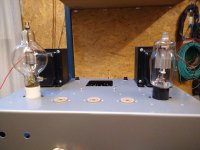
I have an 811a amp that's in the final stages of a rebuild from a working prototype to a finished "tidy amplifier" There's a pair of Hammond opts and it will use Coleman regulators (they're in the post)
Here's the problem: I just came across a pair of 100TH valves in nos condition... The schematic I used is attached below. I am happy how it works for 811a's. When I built the amp I ended up with about 470v for the 811a plates.
Could I sub in the 100Th and keep the 6v6 drivers?
The output transformers have a UL tap at 40% that may be close to 3.5k
Any thoughts out there? I think the 100TH is a great looker!
Attachments
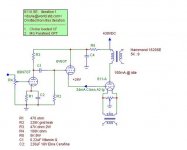
Very unsuccessful scheme with 811a. To slightly correct this shortcoming, you need to enter an additional voltage source -100V and connect to it from the cathode 6V6 resistance of 10-15 k. Mode 6V6 will have to be adjusted.
450V very low supply voltage for 100TH.
450V very low supply voltage for 100TH.
Yes I was sceptical and infact ran a higher HT voltage (540v) just in case. This was built 10 years ago on a shoestring budget with zero test equipment except for a multimeter.
I was amazed how well it worked I honestly thought it would not work. Every component was used as drawn although as I ran the higher HT voltage for the plate I adjusted resistors to maintain correct voltages for the driver and preamp valves.
Any other builders of this circuit please chime in.
As for the -100v mod/upgrade? Understandably that sounds plausible have you done this yourself?
I just look at the 6v6 cathode directly to the 811a grid in shake my head and think what?
I have read plenty of comments suggesting this thing won't work. All I can say is it did, it sounded good, better than my 2010's Rotel solid state power amp (funnily on vinyl more than cd, both amps used same Preamp and loudspeakers....)
My day job is audio engineering so I get to use all the nice toys "sounds good" for me means on par with the good pro stuff or pleasing and articulate, not loose, muffled, flat or blurry. My speakers may have helped it sound tighter than it is, who knows it was working for me. Being unscientific about sound quality is a subjective rabbit hole I don't want to head down with this post. These were my observations.
Power output was unknown but I am confident I was getting 6-8w of clean power.
As one of those "working prototypes" there were issues with the PSU running flat out and hot! As well as no safety cage! 10 years later I have young children..
With the new build I intend to dummy load the amp and get some solid figures, hopefully distortion figures as well.
New build - Coleman regs going in
-same 400vac HT, and probably a 450vac tap
-far superior output transformers 5k Hammond 1628 SEA
-new chassis
-new psu transformer
I have seen similar arranges, using an EL84 to drive a G2-driven EL509 (modified Synola), seem to work fine according to people who tried it.Very unsuccessful scheme with 811a. To slightly correct this shortcoming, you need to enter an additional voltage source -100V and connect to it from the cathode 6V6 resistance of 10-15 k. Mode 6V6 will have to be adjusted.
450V very low supply voltage for 100TH.
Very unsuccessful scheme with 811a. To slightly correct this shortcoming, you need to enter an additional voltage source -100V and connect to it from the cathode 6V6 resistance of 10-15 k. Mode 6V6 will have to be adjusted.
450V very low supply voltage for 100TH.
I've built that design and it works fine. The 811a needs positive grid voltage and can take 30ma or so.
I will not argue, this development really works. If you have not directly compared with other design of the amplifier, you have the following opinion.I've built that design and it works fine. The 811a needs positive grid voltage and can take 30ma or so.
I made and compared different amplifiers on 811a, I prefer this design http://www6.plala.or.jp/Michi/811a24wseamp_0812.html
I recommend you try it.
Yes I have looked at that schematic in the recent past and gone over the full webpage. Upon starting the rebuild (infact I think I have found nearly every schematic out there) I was forced to keep the count of parts low and cheap to stay on a shoestring budget and still am. The Hammond opts were purchased 5 years ago after much saving..
I have found a few very similar schematics also some with this topology using a 6l6 triode connected driving a 100th or 811a. The 6v6 is not a common driver from my research.
When I look at this schematic I can only assume that the 6v6 cathode goes positive due to the 811a grid having resistance to the negative HT rail. If this so my thoughts are a 6v6 may run out of plate dissipation driving a 100th or 811a to full power 10-20w. Or more simply to get more than 8w out a 6l6 is needed.
I will rebuild using the same schematic and layout as before for a 811a. If I do drop in a 100th am I correct that my circuit topology may result in the tube under performing and not going into melt down from being fully turned on?
These kinds of designs have critical weaknesses, and aren't for the faint of heart. They're critically dependent on a combination of DC coupled driver valve and output valve unique bias voltages (varies with individual valves, aging, etc.). The output valve's grid is a terrible load for the driver valve, low and non-linear. The output impedance is high, causing large frequency response variation with real speakers' loading impedances. Etc. A lot of unacknowledged problems for what looks, to the innocent eye, a simple circuit. Just say no.
All good fortune,
Chris
All good fortune,
Chris
Thanks Chris,
this is really informative, I may have got lucky with my last opt transformer and loudspeaker combo...
Going forward I will give it another go then measure the results and eventually get them back into this thread. For this build I'm staying committed to the chassis layout.
This is a logical progression with my layout:
http://www6.plala.or.jp/Michi/811a24wseamp_0812.html
I don't have any 6998's in the collection, I do have plenty of 2c34s...but I doubt they're adequate.
Tim
Curves for 100TX show that at voltages less than 1000-1500V distortions will be very high. Try to check it if you are ready for it.I will rebuild using the same schematic and layout as before for a 811a. If I do drop in a 100th am I correct that my circuit topology may result in the tube under performing and not going into melt down from being fully turned on?
I used two 6C19P with great result.I don't have any 6998's in the collection, I do have plenty of 2c34s...but I doubt they're adequate.
Tim
No. Impedance is transformed by (turns ratio)² x RL.The output transformers have a UL tap at 40% that may be close to 3.5k
So 40% tap is 0.4² x 5000 = 800 Ohms. If 60% tap is used, then 0.6² x 5000 = 1800 Ohms.
Yes that does look correct with the impedance my bad. I'm not particularly keen leaving out a large chunk of windings on a transformer. From previous experience changing the secondary load to mismatch the transformer taps ie. 8 ohm on 4 ohm winding or 4 ohm on 8 ohm winding is often a workable solution, Ideal no.
Yes 1000v is out of the question for the meantime, the PSU always put me off pricewise and size.
If a 811a looks like a 1k load to the driver tubes cathode, does anybody know what the 100th may present? I'm going to get into the shack tonight and crunch those numbers regarding the approx 1k load.
Tim
You select the tube mode and look at the curve grid current. Then Ohm's law.I have looked at this sheet how do I calculate this?
I've been using a 100TH with a 5k transformer and getting great results, but I use local feedback to lower the output impedance of the output tube. An optimal operating point to get max power out with the 5k transformer is about 750V B+ and 125mA. I'm getting over 35W output. I'm running the tube at about 94W plate dissipation.
The challenge with the 100TH over the 811A is the poor saturation characteristics of the 100TH. You cannot pull the plate voltage as low, no matter how much grid drive you give it. It can be subbed into the place of the 811A with appropriate bias voltage and driver rail tweaks (if necessary), but it will produce less power since the plate cannot be driven as low. One half of the wave will clip earlier than if an 811A were there.
Another challenge is that the 100TH was designed with special materials on the plate that purify the vacuum, but those materials need to be very hot to do their job, so the tube needs to be run somewhat close to maximum dissipation (see my avatar for what that looks like). The 811A uses more standard materials for this deposited on the inside of the glass, so this is not a requirement for the 811A.
Are you sure the 100TH you have are in working condition?
Just some stuff to think about...
Yes you gave nailed all of my thoughts on subbing them in, that's how I thought it would behave.
The pair I have show zero black deposits on the glass, the filaments read well. And no rattling sounds. Honestly from all reports they are new. I've seen plenty on evil bay with dark glass etc..
As for firing them up to test, there's plenty of info out there but who to follow...
I'm suspect on running the heaters alone without grid and plate current below red plating. I know they need to be ran at their ratings. Tantalum for the plates is a really interesting material.
I think a dedicated test rig for "restoring" them is needed. Tubelab? talks about his big variable PSUs on the test bench
- Home
- Amplifiers
- Tubes / Valves
- 100th or 811a?