Hello,
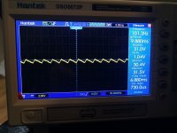
I just repaired a Marantz Pm94 that had failed output transistors and now I have a 100hz snore sound at the output.When I measure the power rails on the 2 27000uf capacitors I do have a noise of 100hz on this part of power supply. I measured the esr of the capacitors 27000uf with the atlas peak tester esr and I find 0.04 ohms .On the 2 capacitors 18000uf the power supply and normal no noise .On the other hand the voltages are slightly different from the manual service on the 2 rails of the capacitors of 27000uf I have 32v instead of 28v and on the 2 capacitors of 18000uf I have 65v instead of 67v , is this normal?
I just repaired a Marantz Pm94 that had failed output transistors and now I have a 100hz snore sound at the output.When I measure the power rails on the 2 27000uf capacitors I do have a noise of 100hz on this part of power supply. I measured the esr of the capacitors 27000uf with the atlas peak tester esr and I find 0.04 ohms .On the 2 capacitors 18000uf the power supply and normal no noise .On the other hand the voltages are slightly different from the manual service on the 2 rails of the capacitors of 27000uf I have 32v instead of 28v and on the 2 capacitors of 18000uf I have 65v instead of 67v , is this normal?
Attachments
ServMan's gives production values, consider +/-10% on power rails are ok.
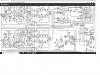
The 100Hz snore is not wanted. But if rails are ok, where is the rectified 50Hz induced in the amp? The scope indicates charging-discharging, but that's not the ac-dc rectifier. Can you post part of the ServMan (circuit-part) public or the whole pm?
My guess now is an odd ground loop or failing rail-cap somewhere in the front stages.
Both channels?
The 100hz is on the power rail of the 2 capacitors C002 27000uf after the diode bridge D002 . Power rail D001 and capacitors C001 are normal .
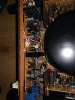
All the capacitors in the amp were replaced except the 4 main power supply.
Cordialy
All the capacitors in the amp were replaced except the 4 main power supply.
Cordialy
Attachments
There is no Marantz service tech still alive, they've been lost desolated in labyrinthic confusion. Or lost confused in desolated labyrinths. Or lost in confusing labyriths desolated.
This will take ages to decompose the origine of the magical 100Hz snore-oscillator.
My eyes are already bleeding peeking only oblong to it. DMAF, and send the ServDoc or whatever direct pm.
This will take ages to decompose the origine of the magical 100Hz snore-oscillator.
My eyes are already bleeding peeking only oblong to it. DMAF, and send the ServDoc or whatever direct pm.
It would be interesting to know what was originally found to be defective and how the repair went. Has idle current been set to spec again? Does it measure OK otherwise?
1 Vp-p is not an inordinate amount of ripple on a 30 V supply, but it certainly isn't exactly "idle" either. Loading in idle should be about 600 mA, but this is a supply that should be capable of 10 A or thereabouts.
So it's either
a) excessive current draw in idle (which should coincide with heat being generated and corresponding power consumption)
or
b) in fact aged capacitors. Measuring ESR in the tens of mOhms is not entirely trivial, so I would take the 0.04 ohm reading with a grain of salt. You can still buy 22000-33000 µF / 40 V caps with 10 kHz ESR ratings in the 20s or 30s of mOhm though, so it wouldn't seem wildly off at the very least.
Is the ripple visible on both positive and negative 30 V supplies equally? That would point to (a).
Also, how much buzz is there at the output? I would normally expect a PSRR of maybe 100 dB from a circuit like this, so 1 Vpp should give 10 µVpp. That would not be audible, in fact, so something may still be amiss - and if it's just a bad ground connection somewhere.
Does this affect both power amplifiers equally? (It's definitely the power amps themselves, not previous stages, right?)
Hello,
I just got back on my amp and found that by disconnecting the power from the preamp board there is no noise.I changed all the capacitors, check all the ground but I don’t know where to look.The initial failure was the transistors of a channel that was hs, I replaced it with 2sk1529 and 2sj200 equivalents. I set the bias and replaced all the capacitors, if anyone has an idea ?
Cordialy
Attachments
It would be interesting to know what was originally found to be defective and how the repair went. Has idle current been set to spec again? Does it measure OK otherwise?
1 Vp-p is not an inordinate amount of ripple on a 30 V supply, but it certainly isn't exactly "idle" either. Loading in idle should be about 600 mA, but this is a supply that should be capable of 10 A or thereabouts.
So it's either
a) excessive current draw in idle (which should coincide with heat being generated and corresponding power consumption)
or
b) in fact aged capacitors. Measuring ESR in the tens of mOhms is not entirely trivial, so I would take the 0.04 ohm reading with a grain of salt. You can still buy 22000-33000 µF / 40 V caps with 10 kHz ESR ratings in the 20s or 30s of mOhm though, so it wouldn't seem wildly off at the very least.
Is the ripple visible on both positive and negative 30 V supplies equally? That would point to (a).
Also, how much buzz is there at the output? I would normally expect a PSRR of maybe 100 dB from a circuit like this, so 1 Vpp should give 10 µVpp. That would not be audible, in fact, so something may still be amiss - and if it's just a bad ground connection somewhere.
Does this affect both power amplifiers equally? (It's definitely the power amps themselves, not previous stages, right?)
Yes the ripple on the 30v power supply and the same on the 2 positive and negative rails, the amp operates in class A on the 35w and goes to class AB up to 140w . I measured in class A ripple and as the image has the 1v oscilloscope and in class AB approximately in 500 to 600 ma .65v rail on 18000uf capacitors is stable ,Consumption on the 30v rail in class A and 2.8 A and in AB 800ma
Last edited:
So it is the preamp that's giving us trouble.Hello,
I just got back on my amp and found that by disconnecting the power from the preamp board there is no noise.I changed all the capacitors, check all the ground but I don’t know where to look.
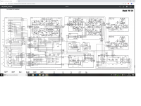
Please test whether TONE DEFEAT makes a difference - that would rule out the tone amp. Any difference when using phono?
Next step, have you looked at the preamp supplies already? Rectifiers and regulators are on the PG00 board. +/-28 V unregulated, +/- 21 V regulated. Would not be surprised to find a few degraded caps there. It would have to be pretty bad to get through the regulator and the extra passive filtering.
If the supplies actually turn out to be clean, I would turn my attention to the shields in the signal path, especially the PK00 - PQ00 (Main Volume) - PG00 route. Does touching something there make any difference?
- Home
- Amplifiers
- Solid State
- 100hz noise on Marantz PM94