They are these https://www.ascapacitor.com/full-product-list/x386s-x387s-x388d-x386d.html Oil filled PP.440 VAC? Normally that has a 630V DC rating, if it’s a film type cap. With electrolytics I wouldn’t count on it. Bipolar electrolytics shouldn’t be used for DC, as one of the internal cap pair is always going to be backwards. My guess is @tonescout is using MKPs. It has that look about it.
That's a nice looking amplifier, very professional
Mine is more of a home made style,
Rich
Attachments
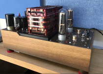
Very well made.....but a few questions:
- What is this big cube in the middle of the amplifier? Power transformer or output choke?
- Why doesn't it have a cover?
- The two 211s are Nos type, probably GE...which aren't cheap either. But why are the drive tubes cheap?
- Why are the volumes between the tubes? Are they volumes?
- The best place for the oil capacitors is directly after the rectifiers.
This is point from technical audiophiles. Oil capacitor after the rectifier tube for better results. In the picture above, a famous Japanese amplifier uses this method.
seen from the underside of the amplifier hereView attachment 1433034
Very well made.....but a few questions:
- What is this big cube in the middle of the amplifier? Power transformer or output choke?
These are 2 very large Partridge (ex Partridge people set up after Partridge closed down) output transformers
they are too big for a cover unless I try to hime make one, and I am not a metal working guy. and also my experience is sometimes covered transformer loose a little dynamics
- Why doesn't it have a cover?
211 GE, driver tubes 6C45. This is the circuit, comments welcome
- The two 211s are Nos type, probably GE...which aren't cheap either. But why are the drive tubes cheap?
Because my original design was to copy the Onkagu circuit and this is a place for a second valve repurposed. I was not very capable/knowledgable when this was first made 25 years ago, and a guy I knew ended up 'finishing' it for me, BUT completely changed the amplifier design to his (above).
- Why are the volumes between the tubes? Are they volumes?
I put the volume pot in to see if (as my friend does) I like a balance between preamp volume control and power amp volume control. However for whatever reason my volume control has a ZZZZZZ when it is not on full volume. I use it at full volume and control the sound levels from my preamplifier and leave this on full gain. It is occasionally useful to turn the power amplifier down without turning it off.
- The best place for the oil capacitors is directly after the rectifiers.
This is my Power Supply circuit I am now installing as the original uses a 4 stack of 400V 220uF electrolyctic to get to 1000V
I will use Shizuki ASC386S 45uF with PIO Arizona blue 0.47uF and an ultiamte Ruby Mica 0.016uF on the first caps.
Comments again welcome,
Rich
Some thoughts:
I wouldn't speculate as to the DC voltage rating of the ASC; being metal can increases the hazard. The modern DC Link capacitors are Polyprop film, compact, have high voltage ratings, are available cheap in a range of UF. For safety I'd go with those instead rated at least 1.2+Kv, need to allow for main voltage fluctuation and unloaded transformer voltage.
I wouldn't use carbon comp there. Their voltage rating may not hold up over time as they absorb moisture and drift. I'd use a number of metal film in series. Also 4M7 is too high. I've seen 50/C max recommended. I'd also include an LED or neon to indicate the presence of any residual charge.
I'd also include a HT softstart on the primary (NTC & relay) as you're using directly heated rectifier. That might extend the life of your 211's and allow a smaller fuse.
I don't see a reason to do CLLLCCC . CLCLCLC would be more usual.
Whats the halfwave valve with a resistor load for/ simulating ?

One of the members made a mistake about the 450 ac v capacitor and I replied that cap is ac v ... and this kind of voltage is common in the oil cap . Now I made a mistake again my self . This 450 volts is very common in electrolyte cap . so how abut humin speaker ?
Some thoughts:
I wouldn't speculate as to the DC voltage rating of the ASC; being metal can increases the hazard. The modern DC Link capacitors are Polyprop film, compact, have high voltage ratings, are available cheap in a range of UF. For safety I'd go with those instead rated at least 1.2+Kv, need to allow for main voltage fluctuation and unloaded transformer voltage.
I wouldn't use carbon comp there. Their voltage rating may not hold up over time as they absorb moisture and drift. I'd use a number of metal film in series. Also 4M7 is too high. I've seen 50/C max recommended. I'd also include an LED or neon to indicate the presence of any residual charge.
I'd also include a HT softstart on the primary (NTC & relay) as you're using directly heated rectifier. That might extend the life of your 211's and allow a smaller fuse.
I don't see a reason to do CLLLCCC . CLCLCLC would be more usual.
Whats the halfwave valve with a resistor load for/ simulating ?
Thanks for the input, I have had the ASC oil polyprop film capacitors for a while, and used them on a preamp and I like their sound (better than the electrolytic type they replaced there).
The existing set up has been working fine for 25 years and uses carbon 1/2 or 1 watt Allen Bradley at 910K across each 220uF capacitor.
I am not sure what 50/C calculates - is this balance resistor in MOhms?
The over current protection is 3A, I like these from my experience they sound better than a conventional fuse.
CLCLCLC makes a considerably slower power supply using PSUD2, really CLLLCCC is CLC
The half wave is simulating the supply at 500V stepped down by a 10K for the supply to the PC645 valve, the measured values and simulation seem to tie up.
Thanks,
Rich
If you use PSUD2 and see the speed of the power supply to changes in current demand you will recognise it's a balance. CRCRCRCRC etc. is slower to respond, but reduces noise more. It's a hypothesis/experiment as mine currently is CLCLCLC and I am hearing and seeing 20-30 seconds for the system to come up to voltage, I think that will slow the musical dynamics compared to a simpler CLC design. I am influenced by the infamous Ongaku amplifier and other iconic designs which don't have a cascade, and the CRCRCRC design is for voltage control at each sage as well as lowering the noise.
It is relatively easy for me to change the stages as the circuit is laid out in a way that i can be retrospectively changed if the noise is too high. The capacitor pack is on a sub assembly bolted to the bottom of the amplifier (mainly to allow packaging of very large capacitors!)
It is relatively easy for me to change the stages as the circuit is laid out in a way that i can be retrospectively changed if the noise is too high. The capacitor pack is on a sub assembly bolted to the bottom of the amplifier (mainly to allow packaging of very large capacitors!)


With these parameters the HV PSU is very lazy (about 800ms r. time).
Set a goal to -about- 400ms recovery time (90% to 10%, and vice versa).
IMO absolute unnecessary the three series connected choke. The simulated 22mVpp hum is in the preamp territory, large amplifiers working well even with significantly greater disturbance too. Usually 10H is enough for "fast" PSU.... with larger hum.
For example Ongaku use only 3H 250mA choke.
If you want to reduce PSU output hum, additional L-C filtering is imaginable.
The bottleneck of HV PSU usually is the PT.
If in you sketch the PT is one transformer, the 5V filament coils is the most dangerous parts.
The HV coil's unloaded and loaded (with assumed load, which would be more greater than static output current) voltage and its resistance restricts the PSU output voltage.
As others have written, the 4M7 is too large, use smaller (few hundred kOhm). One resistor is very dangerous , use two or three series connected 600V rated metal film resistors.
This is great information, thank you.
So as it happens it will be very easy for me to connect 1, 2 or all 3 chokes on the power supply in the way it is already laid out, as they all join the circuit (or not) at some adjacent solder posts.
The mains transformer is a single unit as per the photo, including the 5V, 6.3V and 10V filament supplies.

For the balancing resistors I was going to Allen Bradley 2W but can put these in parallel and aim for a lower value.
I read this and recognise I don't want to warm everything up with balance resistors supplying heat.
https://va1der.ca/index.phd/balance-resistors-for-series-capacitors/
Thanks again,
Rich
So as it happens it will be very easy for me to connect 1, 2 or all 3 chokes on the power supply in the way it is already laid out, as they all join the circuit (or not) at some adjacent solder posts.
The mains transformer is a single unit as per the photo, including the 5V, 6.3V and 10V filament supplies.
For the balancing resistors I was going to Allen Bradley 2W but can put these in parallel and aim for a lower value.
I read this and recognise I don't want to warm everything up with balance resistors supplying heat.
https://va1der.ca/index.phd/balance-resistors-for-series-capacitors/
Thanks again,
Rich
This is what happens on PSUD2, the speed of response in my layman's understanding is kind of similar.
I have also plotted the current design on PSud2


I have also plotted the current design on PSud2
- Home
- Amplifiers
- Tubes / Valves
- 1000V Power supply question on 211 SET (quick simple one!)