Hello clever people 🙂
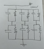
I am rebuilding a 211 Power supply and have the following layout as attached, using 440VAC rated capacitors.
These are the smoothing capacitors that follow a voltage doubler circuit using 2 5u4GB valves to achieve the 1000V, along with some inductors prior to this bank of capacitors.
My question is simple, should I connect the dotted line between the 3 capacitor pairs at the voltage mid point or not?
I hope this makes sense as a question, the answer maybe it does not matter!!
Thanks for the guidance,
Rich
Attachments
If you do and one pair become unbalanced, you may have a problem.
I would say no but why not use capacitors of the correct rating instead.
I would think the capacitance is not high, so PMP types of 1200volt rating would suffice.
Microwave ballast capacitors are rated around 1200v DC of various values.
I would say no but why not use capacitors of the correct rating instead.
I would think the capacitance is not high, so PMP types of 1200volt rating would suffice.
Microwave ballast capacitors are rated around 1200v DC of various values.
Last edited:

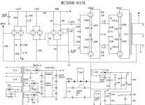
Please show the complete circuit diagram of the power doubler. I recently made 211 amp using the doubler method.
ecc801s---vt25----12bh7-----vt4c--------++2x 5r4 rca+ ez80

ecc801s---vt25----12bh7-----vt4c--------++2x 5r4 rca+ ez80
If you are placing 1kVdc across a series pair of 450Vdc caps, you are overvoltaging them by about 100Vdc, and that could result in capacitor failure.
Sorry, I missed the VAC rating. Should be OK but I would keep the equalizing resistors separate in case one cap goes bad.
Everyone,
Thanks for the information and thoughts.
I will keep the pairs separate, and I am using 2W Allen Bradley balancing resistors at 4M7.
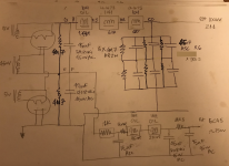
I have changed the 6c45 driver circuit a little but this is similar from an old sketch here attached.
Thanks for the information and thoughts.
I will keep the pairs separate, and I am using 2W Allen Bradley balancing resistors at 4M7.
I have changed the 6c45 driver circuit a little but this is similar from an old sketch here attached.
Attachments
440 VAC? Normally that has a 630V DC rating, if it’s a film type cap. With electrolytics I wouldn’t count on it. Bipolar electrolytics shouldn’t be used for DC, as one of the internal cap pair is always going to be backwards. My guess is @tonescout is using MKPs. It has that look about it.
211s, 845s? Now I know who could use the 2000v CT transformers and matching chokes I have, and which I'll never use. Don't think I could ship the damn things with their weight.
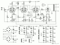
See page 10 of Broskie's blog at
https://www.tubecad.com/2024/06/blog0604.htm
I have not tried it myself and never will. I'm too scared.
ray

https://www.tubecad.com/2024/06/blog0604.htm
I have not tried it myself and never will. I'm too scared.
ray
this circuit for hv in Electrostatic Headphones amp ...not use for tube amp like 211 or 845 ...gm70.....low current
It looks like the current limit is set by the VA rating of the transformers. Broskie specifies two 30 va units which would be fine for electrostatics as you say. I presumed larger 230 VAC transformers would be adequate for 845s. Of course, the 3K resistor (and its power rating) would have to be adjusted depending on the voltage required for the 845s. 230 VAC transformers are relatively inexpensive compared to higher voltage power transformers and easier to purchase.
The diodes have a 1 amp rating.
That is my understanding and if you think I have missed something, I will be happy to find out.
However, if I had a power transformer with a suitable output voltage, I would just use DC Link caps and a choke in the ground leg. It's simpler.
ray
The diodes have a 1 amp rating.
That is my understanding and if you think I have missed something, I will be happy to find out.
However, if I had a power transformer with a suitable output voltage, I would just use DC Link caps and a choke in the ground leg. It's simpler.
ray
It's may working .... with larger toroid transformers (higher wattage, low secondary DCR) ... and large sawtooth swing on the 1kV DC. 😕this circuit for hv in Electrostatic Headphones amp ...not use for tube amp like 211 or 845 ...gm70.....low current
So another -costly- filtering necessary.
No free lunch.
- Home
- Amplifiers
- Tubes / Valves
- 1000V Power supply question on 211 SET (quick simple one!)