I did try it again and all seemed well so could have been a temporary 'funny'.
You get a lot of those on the net!
You get a lot of those on the net!
Hi tca
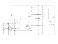
The original board is around somewhere but this is the schematic as far as I recall. I remember that the feedback capacitor only needed to be small, and I got almost 1 MHz bandwidth out of it. The input capacitor is just to make sure there is a low impedance on the base of the input transistor at HF. You could select high gain transistors (BC337-25 or -40) and reduce the driver (VAS) current, but if you do that I would shift the compensation capacitor to the output rail. As far as I recall this works and reduces crossover but with 100 MHz output transistors crossover distortion is pretty low anyway.
In many respects this is almost and ideal amp. The only issue is that it can only do 1W!
I'll search for my original board and let you know if there is any difference in the compensation network.
I know some American colleagues might say "2N2222" but with the plastic transistors you can put the output transistors and bias stabiliser between two aluminium plates to hold the temperatures closer without needing insulators etc.
I would not recommend the 2N5401 - it's a nice little 150V transistor but has a lower minimum gain than the BC237 (or BC547) etc.
John
Attachments
I want to try this circuit for my next project (maybe). I'm looking to build a small IC-less that works with 9/18 volt supply.
Thanks,
Sergei
Thanks,
Sergei
Why not try something original for a change:
Here is an example based on a TL431 used as a supertransistor.
When built, it will look exactly like an ordinary discrete transistors amplifier, but with exceptional performances:
- Status
- Not open for further replies.