I am working on a design that employs a pair of 15" drivers in vertical alignment. This configuration provides some vertical dispersion control but of course due to their physical spacing unless one is filtered out, lobbing will occur above 250/300Hz.
I understand jbl do this with one/some of their designs. My question to the forum is this. If you are only going to deploy a simple first order low pass on one driver and run the other full range up to its upper crossover what would be the combined effect in terms of phase and response throughout the "pass band".
I understand that a 6dB/octave lp filter lags at 45 degrees but the second driver will be running full range to its upper point with no hp filter.
I assume of course they will sum at the bottom end where both are active but will there be response anomalies throughout the crossover region or will they remain in phase and sum output?
Thanks!
Last edited:
but will there be response anomalies throughout the crossover region or will they remain in phase and sum output?
Very likely have anomalies in response.
Do you have center/center spacing determined? If yes could you give it as well as FC you plan. I could run a sim of vertical behavior.
I can run simulations of the driver interference patterns or lack of them. They will be close spaced with centres just 1.5ft apart. I can assess the frequency I need to cross the lower one out by plotting the polar responses. Filtering one out at 200Hz certainly produces a good polar response without lobing.
My question was more about the effect of the filter itself. As it only has a 45 deg phase shift (6dB/oct LP) but is only working on one driver, do the two drivers, one "full range" and one filtered still sum at low frequencies where they are both working covering the same frequency range....?
Cheers..
do the two drivers, one "full range" and one filtered still sum at low frequencies where they are both working covering the same frequency range....?
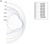
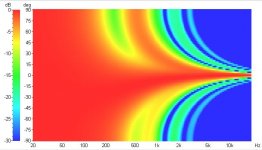
From the sim i've done using data you gave (including filter) yes, but i would not say they are not lobing in vertical... above 200hz there is a nice -15° lobe.
Edit: -7.5° lobe, my bad.
Last edited:
Here are the sim ( 1.5ft center to center, 15" driver, 1pole 200hz butterworth on the lower one).
Edit: here is an other sim done by another one. Take a look p 11. From him, using FIR could correct the issue, but i can't sim it.
http://jimmy.thomas.free.fr/temp/DI-BOOMER-TH4001.pdf
Edit: here is an other sim done by another one. Take a look p 11. From him, using FIR could correct the issue, but i can't sim it.
http://jimmy.thomas.free.fr/temp/DI-BOOMER-TH4001.pdf
Attachments
Last edited:
Brilliant. Very helpful. Thank you for this. My software predicted a tilt but not with this accuracy. I probably need your software package!
It may be some error in what i simulated: i used standard radius for a 15". It will probably be more accurate if you give SD from your 15"to determine radius.
What do you plan to use for hi freq and which fc to 15"?
What do you plan to use for hi freq and which fc to 15"?
Last edited:
SD is 855cm^3. Radius in ins =6.49 with the centres still 18" apart. You are getting great results, thank you. What is the software package. Looks like I could do with it!! The upper 15" is actually a coaxial, but the same diameter as the lower unit.
Last edited:
LspCAD.
I could run another sim: which freq range do you want to see in it?
edit:
Nice idea. I like it! 🙂
Not sure about a 1.5 way. I think you could gain from taking out from coax bass duties: much less movement so lesser intermodulation of the high parts from the cd (because cone is usually used as a 'rude' horn if it's a Tannoy kind of coax). If a Altec style you could still improve on the mid from taking the bass out. Tannoy System 215 is a 2way. But that's my point of view.
The issue i see with a 1.5 is that at 1khz the lower 15" will still output freq you could still hear.
Well i will do another run of sim.
I could run another sim: which freq range do you want to see in it?
edit:
The upper 15" is actually a coaxial, but the same diameter as the lower unit.
Nice idea. I like it! 🙂
Not sure about a 1.5 way. I think you could gain from taking out from coax bass duties: much less movement so lesser intermodulation of the high parts from the cd (because cone is usually used as a 'rude' horn if it's a Tannoy kind of coax). If a Altec style you could still improve on the mid from taking the bass out. Tannoy System 215 is a 2way. But that's my point of view.
The issue i see with a 1.5 is that at 1khz the lower 15" will still output freq you could still hear.
Well i will do another run of sim.
Last edited:
That would be very kind! The upper coaxial has its own manufacturer's network which is already tweaked for flat response, but it crosses at 1k8 where of course the cone will be directional. The horn section is 60deg so I imagine the 15" will have narrowed to around that. Their published response and polar plot looks excellent. (Beyma 15AX400fe)
Ok, you cross higher that i would had think for a 15" but given the 60° directivity it is understandable does it have a horn Altec style?
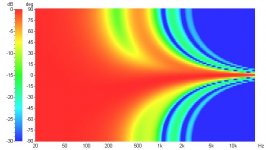
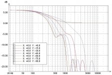
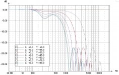
Nevertheless here are the sim. I added some horizontal plot for you to have a better idea of what happen.
edit😛olar map missing...
Nevertheless here are the sim. I added some horizontal plot for you to have a better idea of what happen.
edit😛olar map missing...
Attachments

Done.
...and by the way you're not doing 1.5 way but more a 2.5! 🙂 And tannoy 215 are 3 ways, obviously! 😛
...and by the way you're not doing 1.5 way but more a 2.5! 🙂 And tannoy 215 are 3 ways, obviously! 😛
Attachments
Last edited:
Nice spec.
You'll use them in living room? Given the sens it open the way for low watt high quality amps for home use.
You'll use them in living room? Given the sens it open the way for low watt high quality amps for home use.
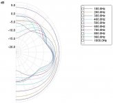
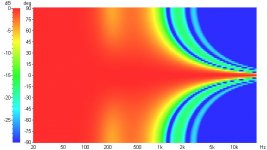
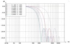
SoundRight, i've done some simulation of the same physical config as before but 3 way using 4pole LR at 188hz ( freq of center/center spacing for 1/4 wavelength).
no more lobing and the attenuation seen in polar map can be used to lessen ground bounce (depending of loudspeaker placement). Look much nicer to me.
😉
no more lobing and the attenuation seen in polar map can be used to lessen ground bounce (depending of loudspeaker placement). Look much nicer to me.
😉
Attachments

Hi, very good of you. Difficult to get away from the zero polar tilt of the LR 4th Order. Plots do look very good as one might expect from this configuration...but it's nice to see the proof! Certainly got me re-thinking the project. Thanks again for your great work and time...cheers!
- Status
- Not open for further replies.
- Home
- Loudspeakers
- Multi-Way
- 1.5 way!