I came across an interesting build, a simple tube buffered LM1876 amplifier. The circuit uses half of an 6922 for each channel, what is the purpose of this? To eliminate cross talk? Is it really necessary? I thought the tube already have septation plate in the middle? I know this topic have been discussed numerous time, but I cant seem find the correct answer. Can anybody tell me?
see the following schematic:
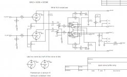
The original article:
Ipod LM1876 amp
see the following schematic:
The original article:
Ipod LM1876 amp
Attachments
That sort of setup makes some sense when types like the 12A_7 group are employed. Then, channel 1 uses system 1 and channel 2 uses system 2. When the sections in use wear out, you exchange the bottles between channels. The center tap in the heater allows cross talk concerns to be dealt with, without loosing 1/2 the value in each envelope. Of course, SY rightly stated that crosstalk concerns are chasing a will o' the wisp.
I came across an interesting build, a simple tube buffered LM1876 amplifier. The circuit uses half of an 6922 for each channel, what is the purpose of this? To eliminate cross talk? Is it really necessary?..
First off it is a tube buffered chip amp. The builder liely does not know that a unity gain buffer add almost nothing to the sound. The "tube sound" only comes with gain.
The only reason I can think of for using two tubes is the "tube rollers" who want to A/B test using a mono signal/ Likely not what the buillding had in mind.
I think He just wanted the tubes for decoration as they are not doing much else. Placebo effect mostly
right on...
I'm learning from all you guys lol
Actually, tube buffers here isolate input impedances of IC that are low and non-linear from input sockets. It is the single plus that I see here, except warmness factor (look and feel). ")
Speaking about shields between halves of tube, they in case of cathode followers are already double-shielded by anodes.
Speaking about shields between halves of tube, they in case of cathode followers are already double-shielded by anodes.
As mentioned, a cathode follower in front of a non-inverting opamp is kind of pointless. The valve buffered gainclone started out as a CF driving an inverting opamp, which at least has a point, even though I'll bet a mediocre CF driving an LM chip is higher distortion than the bare LM chip.
If you really want something special you should try adapting Bob Cordell's work on gainclones to a tube front end (Ch 27 of his latest book).
If you really want something special you should try adapting Bob Cordell's work on gainclones to a tube front end (Ch 27 of his latest book).
Although the ECC88 is quite good on low voltages, 44V is still a bit low so some distortion is almost inevitable. They are there partly for cosmetic reasons, partly to add some distortion (for so-called 'tube sound') and, perhaps, partly to act as an input buffer. Only the designer knows what he intended. I guess his main aim was taking money off people!
Well, you really only have 22V across the tube. And a 5k load resistor. So there will be plenty of distortion. The buffering effect is minimal- iPods have zero problem driving a 10k load, and increasing 10k to 47k is not exactly profound.
I notice that the heater circuit isn't shown. There could be even more, ummm, interesting things there.
I notice that the heater circuit isn't shown. There could be even more, ummm, interesting things there.
I have many unused low voltage transformers. Several ecc88's and 6n23p's too. Sometimes I think about doing something like this:
Tube-buffered gainclone
Waste of time?
Tube-buffered gainclone
Waste of time?

Well, from a distortion standpoint, it's a far better engineered circuit. Unfortunately, that implies that the buffer isn't doing very much to the sound. So I'm not sure what the point is of the added circuitry.
So I'm not sure what the point is of the added circuitry.
He says it sounds better with the buffer, but I also have my doubts. Guess the only way to find out is building it. Not sure....maybe I will find a better use for the transformers and tubes. A guitar preamp. Another thing I don't need.
projects by fanatics, for fanatics.
Yeah, solder fume junkie here.
A difference of only 0.3% can be an amazing thing.
The GC with a buffer definitely sounded better than the GC without it because the soundstage was more clearly defined, vocals were more natural, wind instruments also more defined, piano sounded less aggressive, more balanced and more integrated with the whole sound. Highest tones, which sounded aggressive and irritating on lower-quality speakers, became more pleasant and silky-sounding in the buffered version
I remember seeing and hearing a Gary Dodd tube buffer in front of an Icepower amp. It worked well. The Ice is clean, but distortion is mainly H3. If Gary managed to add some H2 and H4 it might actually make the Ice sound cleaner. Harmonics can mask each other.
The Icepower amps have a fairly low input impedance, 8K, IIRC.
The Icepower amps have a fairly low input impedance, 8K, IIRC.
- Status
- This old topic is closed. If you want to reopen this topic, contact a moderator using the "Report Post" button.
- Home
- Amplifiers
- Tubes / Valves
- 1/2 of the tube for each channel?